Installation
3A0732U 9
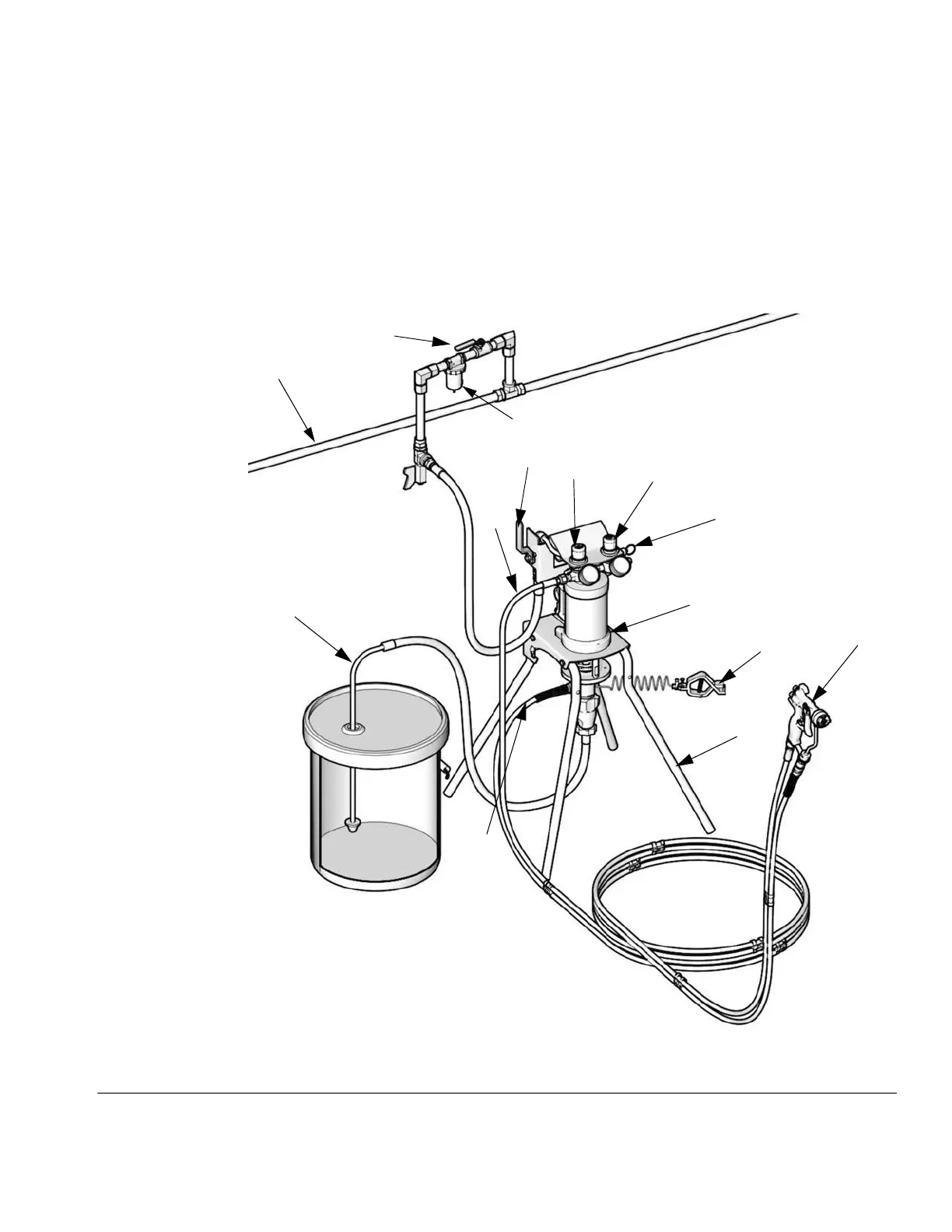
Setup
1. See FIG. 2. Attach one end of fluid hose (K) to pump
outlet (or optional inline fluid filter outlet).
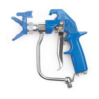
2. Attach other end of fluid hose to gun fluid inlet at
base of gun (H).
3. Attach one end of the air hose (G) to gun air
regulator (E).
4. Attach remaining end of the air hose to air inlet at
base of gun (H).
5. Clip fluid and air hoses together with the supplied
hose clips (qty. of 7). Space clips as needed.
6. Attach the fluid suction kit (J) to the pump inlet.
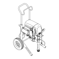
FIG. 2. Typical Installation (Air-Assisted Stand Mount Package Shown)
A
B
C
D
F
E
G
N
J
K
L
ti15591a
H
M
P
Key:
A Main Air Supply Line
B Air Shutoff Valve
C Air Filter
D Bleed-type Master Air Valve
(required)
E Gun Air Pressure Regulator
F Pump Air Pressure
Regulator
G Gun Air Supply Line
H Spray Gun
J Fluid Suction Kit
K Gun Fluid Supply Line
L Pump Ground Wire
(required)
M Mounting Bracket (used for
wall mounting or stand)
N Pump Stand
P Air Pressure Relief Valve