C
A
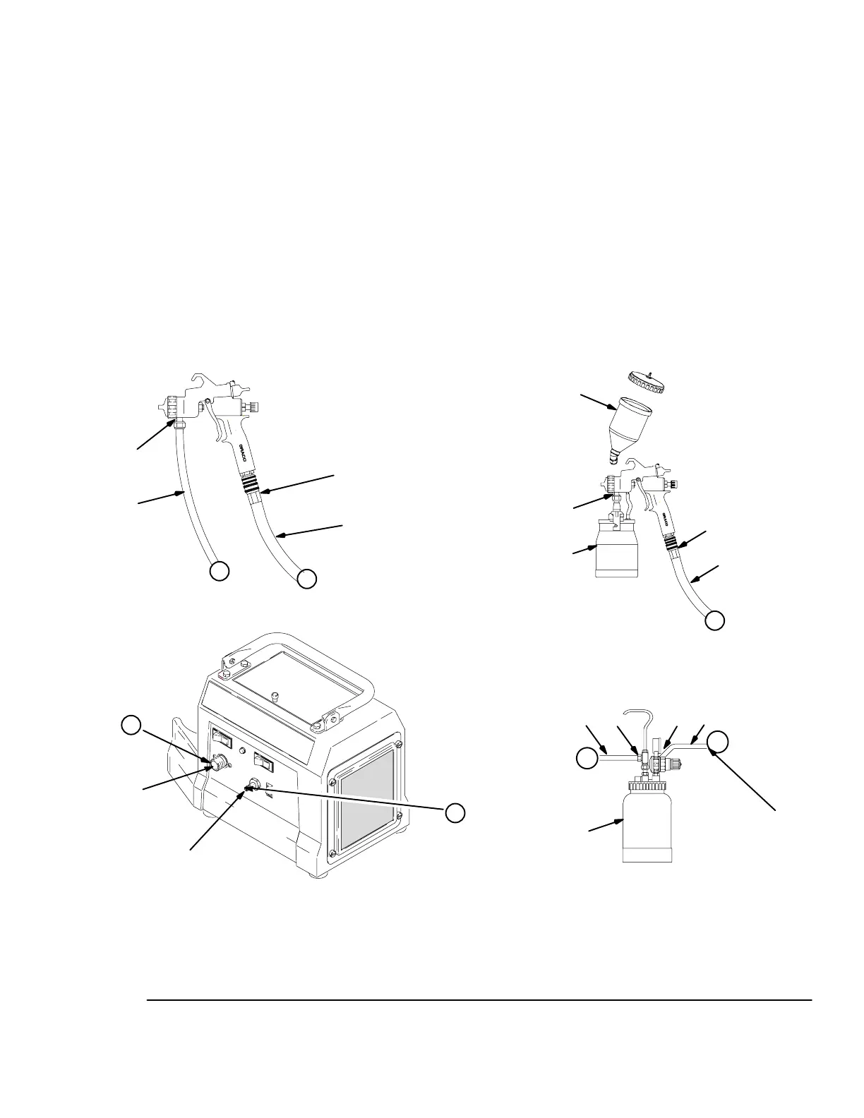
Fig. 3
B
X
A
G
Y
C
X
E
E
D
D
cup-over option
(see manual 309205)
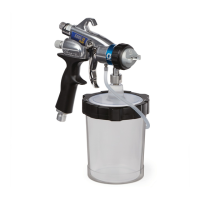
cup setup for spray gun
HVLP 4900 ProCompt
Turbine
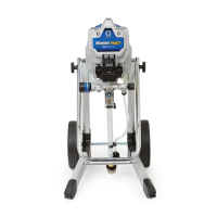
remote pressure pot setup for spray gun
TI0875
X
L
Z
309242 7
Setup
Connect the Fluid and Air Supply
See Fig. 3
D The compressor provides the air supply for the
remote pressure pot.
D The circled letters in Fig. 3 indicate hose line con-
nections.
1. Connect gun air supply hose (A) between turbine
air outlet (B) and gun air inlet (C). DO NOT use
wrench to tighten connections; hand tighten only.
The HVLP 4900 ProCompt turbine uses a quick
connector at outlet (B). A wrench is not required
for hose connection.
2. If using a spray gun cup (D):
Connect the cup to the gun fluid inlet (E).
If using accessory remote pressure pot (F): Con-
nect fluid supply hose (G) between remote pres-
sure pot fluid outlet (H) and gun fluid inlet (E).
Connect pressure pot air hose (J) between pres-
sure pot air regulator inlet (K) and the compressor
air outlet (L).
Connect to Electric Supply
Plug turbine power cord into grounded outlet.
NOTE: Extension cord must be 3-wire, 12 AWG, 50 ft
(15 m) or shorter.
Z
Y
JK
H
G
F
4958C
to
compressor
2-quart remote pressure pot
ti7064a
 Loading...