Service
20 3A5413F
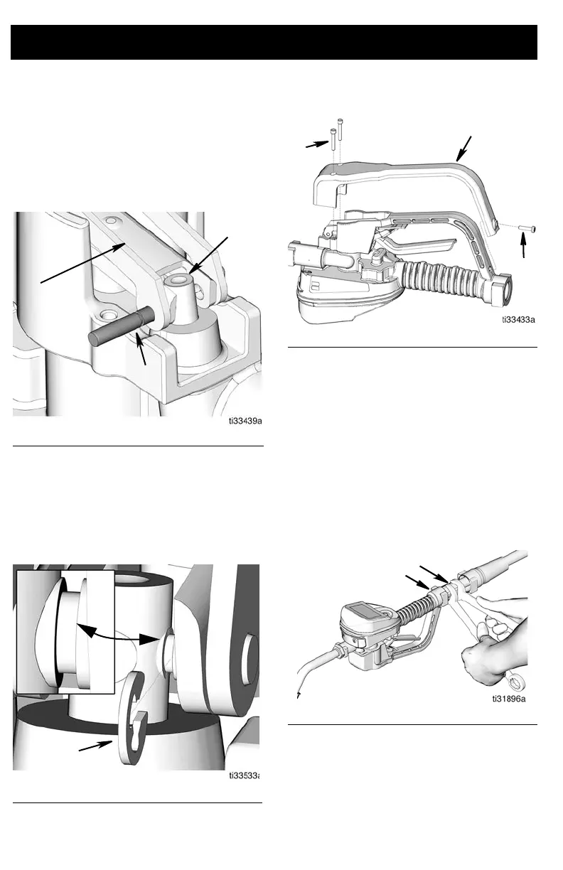
Reassembly
1. Secure metered dispense valve in vise.
Align holes in trigger assembly with
holes in trip rod (27).
2. Install trigger assembly (15) (FIG. 36).
Push pin (15b) through holes in trigger
(15) and trip rod assembly (27).
3. Install clip (15a) as shown in FIG. 37.
NOTE: When correctly installed, the
clip is seated in the groove in the pin
(15b).
4. Install trigger guard cover (16) using
screws (17 and 18) (F
IG. 38).
5. If the metered dispense valve was taken
out of service (disconnected from the
supply hose), apply thread sealant to the
male threads of the hose fitting. Thread
the hose fitting (b) into the metered
dispense valve swivel (6). Use two
wrenches to tighten securely (F
IG. 39).
NOTE: Allow sufficient time for the sealant
cure to according to the manufacturer’s
recommendations before circulating fluid
through the system.
FIG. 36
F
IG. 37
FIG. 38
F
IG. 39