Pressure Control Adjustment
USE EXTREME CAUTION WHEN PERFORMING
THIS ADJUSTMENT PROCEDURE to reduce the
risk of a fluid injection injury or other serious bodily
injury which can result from component rupture,
electric shock, fire, explosion, or moving parts.
.“.
This procedure sets the sprayer
195
bar MAXIMUM
WORKING PRESSURE and sets the overpressuriza-
tion switch (microswitch) to approximately 3600 psi
(242
bar).
Perform this procedure whenever the pressure con-
trol assembly is removed and reinstalled or re-
~
placed, or a new circuit board
is
installed.
.I...”
Improper adjustment can cause the sprayer to over-
explosion. It may also prevent the sprayer from
ob-
pressurize and result in component rupture, fire or
taining the maximum working pressure, resulting in
poor sprayer performance.
ing pressure of
195
bar by performing these adjust-
NEVER try to increase the sprayer’s maximum work-
ments in any other way. Normal operation
of
the
sprayer at higher pressures may result in compo-
justment, however, the sprayer pressure must be
nent rupture, fire or explosion. To perform this ad-
femporari/y increased above the normal working
pressure.
Use a
new
15.2
m spray hose rated for at least
195
bar MAXIMUM WORKING PRESSURE.
A
used, un-
der-rated hose could develop a high pressure leak
or rupture.
NOTE: The following tools and equipment are re-
4.
Place the pump suction tube in a pail of clean
quired for this procedure.
water.
3/8 in. nut driver or 3/6 in. socket wrench
114
in. open end wrench
7/16
in:open end wrench
0
-
350 psi, oil-filled
test
gauge,
Part
No.
102-814
Paii of clean water
Mineral spirits
NEW
high pressure spray hose, Part No.
214-915
5.
Be sure the gun safety latch
is
engaged.
1.
Follow the Pressure
Relief
Procedure
Warning
on page
2.
2.
Refer to the above list
of
tools and equipment
filter and install the fluid-filled pressure gauge
(A)
needed. Remove the plug from the top
of
the fluid
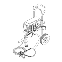
Refer to Fig.
21.
Connect the gun to the new test
hose and connect the hose to the sprayer outlet.
3. Remove the pressure control cover.
Fig.
21
26 307-889
 Loading...