Repair
40 313289W
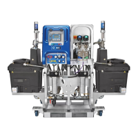
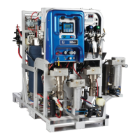
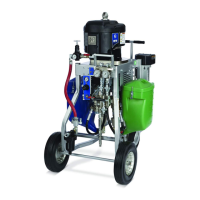
Fluid Control Assembly
Dosing Valve Assembly
1. Follow Pressure Relief Procedure, page 17.
2. Disconnect all fluid lines from dosing valve
assembly (8). See XM Plural-Component
Sprayers Common Parts on page 74.
3. Remove three bolts (16) on back of each dosing
valve (501) from bracket.
4. Unscrew dosing valve housing seats from adapters
on mix manifold.
5. Disconnect RTD (506) from cord grip. Disconnect
pressure sensor (507) and fluid line adapter from
each dosing valve (501).
6. Remove dosing valves. See your dosing valve
manual service and repair instructions.
7. Follow steps in reverse order to reassemble dosing
valve assembly.
Mix Manifold Assembly
1. Follow Pressure Relief Procedure, page 17.
2. Disconnect fluid line and solvent lines from mix
manifold assembly.
3. Loosen four bolts securing mix manifold (508) to
bracket.
4. Unscrew dosing valve housing seats from adapters
on mix manifold.
5. Remove four bolts securing mix manifold (508) to
bracket.
6. Remove mix manifold assembly (508) from bracket.
See mix manifold manual for service and repair
instructions.
7. Follow steps in reverse order to reassemble mix
manifold assembly.
Bracket
16
506
Fluid Line
Adapter
501
ti21278a
 Loading...