Section 3 - Operation
3-18 82104002
Planning A Lift
Note: Lift capacities are based on machine being on a firm, level surface and also
no load being suspended beneath bucket adapter.
1. Determine the weight of the load including weight of slings, chains, bucket/
attachment (tool), and auxiliary lifting devices. Refer to lift capacity chart for
weight adjustment required for bucket.
2. Move the machine to the best position for making the lift.
3. Perform an unloaded trial run of lift to determine maximum boom height/depth
and load radius required to complete the lift.
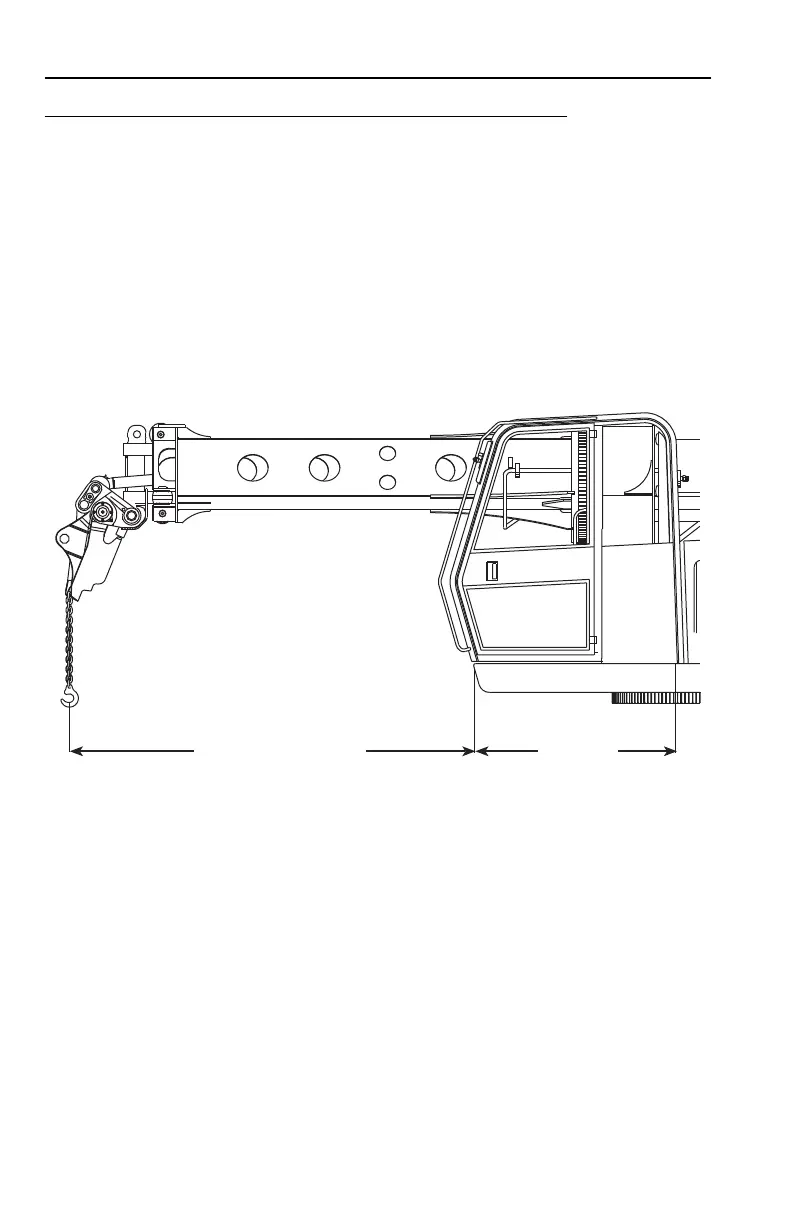
4. Measure boom height/depth from hole in adapter to ground level (same level as
bottom of tire). Be sure to allow for length of chain and height of load.
5. Measure load radius from inner corner of frame at front of cab to vertical load
line (as shown above) and add distance to center of rotation (57 inches).
6. Refer to lift capacity chart column for required load radius. If required radius is
between columns, use column for next larger radius.
7. Check the appropriate capacities for required boom height/depth. The smaller
of these capacities is the maximum load permitted for lift conditions.
Note: To determine working load limits the operator must also consider wind,
hazardous conditions, experience of personnel and proper load handling.
OAC2300
MEASURE THIS DISTANCE
57 INCHES