P a g e | 17
HT812/HT814 Administration Guide
Version 1.0.9.3
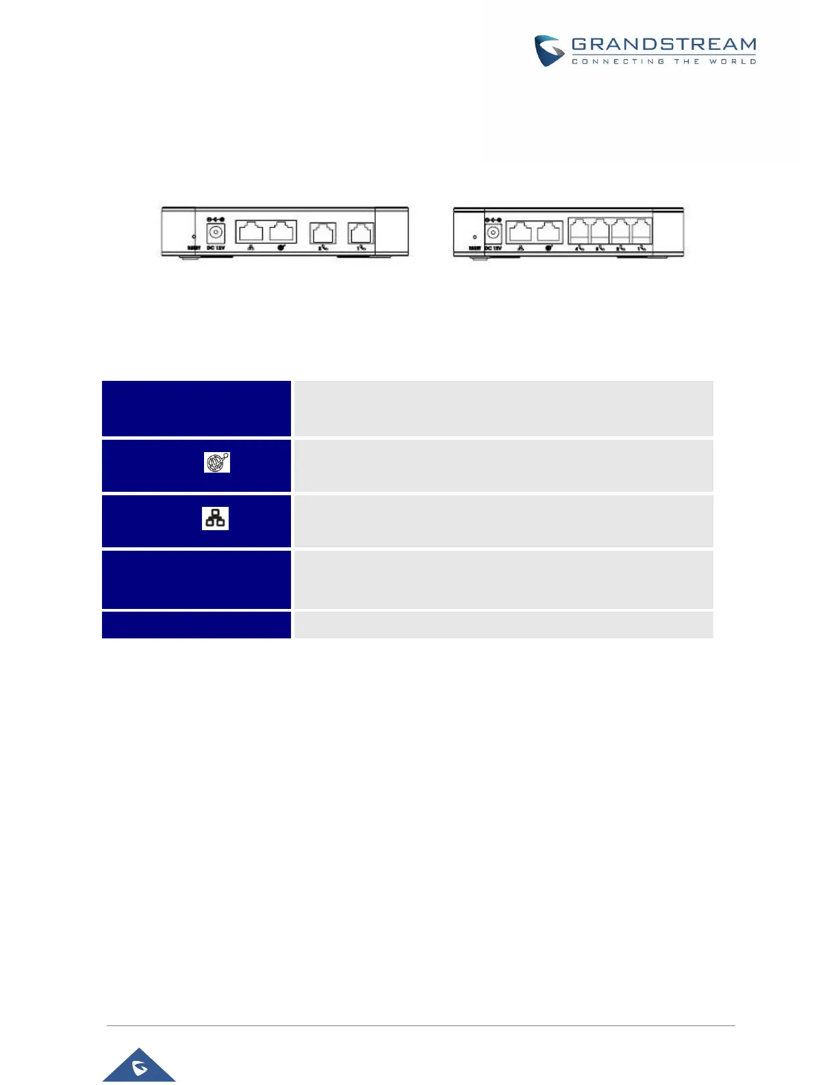
HT812/HT814 Ports Description
The following figure describes the different ports on the back panel of the HT812/HT814.
Table 3: HT812/HT814 Connectors Definitions
Connecting HT812/HT814
The HT812/HT814 are designed for easy configuration and easy installation, to connect your
HT812/HT814, please follow the steps below:
Scenario 1: Connecting the HT812/HT814 using WAN Port
When connecting HT812/HT814 using the WAN port, they will act as simple DHCP Client.
1. Insert a standard RJ11 telephone cable into the phone ports and connect the other end of the
telephone cable to a standard touch-tone analog telephone.
2. Connect the WAN port of the HT812/HT814 to a router, switch or modem using an Ethernet cable.
3. Insert the power adapter into the HT812/HT814 and connect it to a wall outlet and make sure to
respect the technical specifications of the power adapter used.
4. Power, WAN and Phone LEDs will be solidly lit when the HT812/HT814 is ready for use.
Phone 1 & 2 (HT812)
Phone 1,2,3 & 4 (HT814)
Connects the analog phones / fax machines to the ATA using an
RJ-11 telephone cable.
Connects the ATA to your router, switch or modem using an
Ethernet RJ45 network cable.
co
Connects the ATA to your PC or switch using an Ethernet RJ45
network cable.
Connects the ATA to PSU
(12V – 0.5A for HT812) and (12V - 1A for HT814).
Factory reset button. Press for 7 seconds to reset factory default
settings.
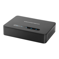
Figure 3: HT812 Back Panel
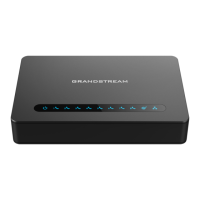
Figure 4: HT814 Back Panel
 Loading...