Section 3: Oil Storage and Supply SystemPage 10
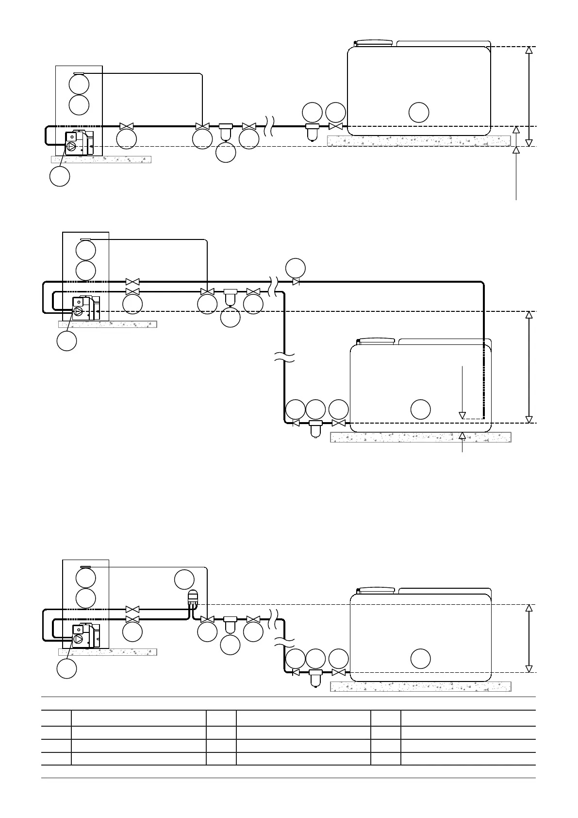
Figure 3-1: Single pipe (gravity) system
Figure 3-2: Two pipe system
Figure 3-3: De-aeration device system
1
23
2
6
9
7
4
8
5
3.5m Max
150mm
9
11
1
2
3
2
6
7
4
8
5
4m Max
300mm
11
123
2
6
9
7
4
8
5
11
3.5m Max
10
Key to oil supply diagrams
1 Oil tank 5 Oil lter (15μm max. ltration size) 9 Non-return valve
2 Isolating valve 6 Fire valve sensor 10 De-aerator*
3 Oil strainer 7 Oil pump 11 Appliance isolation valves
4 Fire valve to BS5410-1 8 Burner
* Position of de-aeration device must be level with or above the oil pump

 Loading...


