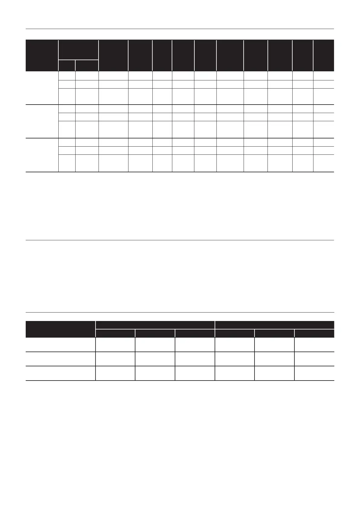
2.3 BURNER SETTINGS
Table 2-3: Burner settings
Boiler
models
(burner
type)
Heat output
Nozzle
Oil
pressure
(bar)
Smoke
No.
Burner
head
type
Burner
head/
air disc
setting
Distance
D ¹⁰ (mm)
Fuel
ow rate
(kg/h)
Flue gas
temp.
(°C)
CO
2
(%)
Flue
gas
VFR ‡
(m³/hr)
(kW) (Btu/h)
External 15/21
External
System 15/21
(Riello
RDB2.2 BX
E15/21)
15.0 51,200 0.45/80°EH 7.5 0 - 1 BX 500 Disc: B 11 1.28 70 - 75 12.5 16.0
18.0 61,400 0.55/60°ES 7.0 0 - 1 BX 500 Disc: C 11.5 1.53 75 - 80 12.5 20.0
21.0 * 71,700 0.60/60°ES 8.0 0 - 1 BX 500 Disc: C 13 1.79 80 - 85 12.5 23.0
External 21/26
External
System 21/26
(Riello
RDB2.2 BX
E21/26)
21.0 71,700 0.60/60°ES 8.0 0 - 1 BX 500 Disc: C 13 1.81 85 - 90 12.5 23.0
23.5 * 80,200 0.65/60°ES 10.0 0 - 1 BX 500 Disc: C 13 2.02 85 - 90 12.5 26.0
26.0 88,700 0.75/60°ES 8.5 0 - 1 BX 500 N/A 15 2.24 90 - 95 12.5 28.5
External 26/35
External
System 26/35
(Riello
RDB2.2 BX
V26/36)
26.0 88,700 0.75/60°ES 8.5 0 - 1 BX 700 N/A 15 2.24 75 - 80 12.5 28.5
31.0 * 105,800 0.85/60°ES 9.0 0 - 1 BX 700 N/A 16 2.67 85 - 90 12.5 34.5
35.0 119,400 1.00/60°ES 8.5 0 - 1 BX 700 N/A 17.5 3.02 90 - 95 12.5 39.0
Notes:
‡ Flue gas VFR: Flue gas volumetric ow rate
1. The data given above is approximate only and is based on the boiler being used with a low level balanced ue.
2. The above settings may have to be adjusted on site for the correct operation of the burner.
3. Gas Oil is NOT suitable for use with Grant Vortex boiler range
4. The ue gas temperatures given above are ± 10%.
5. When commissioning, the air damper must be adjusted to obtain the correct CO
2
level.
6. * Factory settings: 15/21 - 21kW, 21/26 - 23.5kW, 26/35 - 31kW.
7. The combustion door test point may be used for CO
2
and smoke readings only. Do not use this test point for temperature or eciency readings.
8. When setting the 15/21 to 15kW, the air adjuster disc requires repositioning. Refer to Section 10.3 (air adjuster disc).
When setting the 21/26 to 26kW, the air adjuster disc is not required. Refer to Section 10.3 (air adjuster disc).
9. The installer must amend the boiler data label if the output is changed.
10. Refer to Section 10.2 for information on how to set Distance D (Figure 10-5).
2.4 FLUE GAS ANALYSIS
To allow the boiler to be commissioned and serviced, the boiler is supplied with a combustion test point on the front cleaning door.
When this test point is used please note the following:
• The test point is for CO
2
and smoke readings only.
• The boiler eciency and temperature must be taken from the ue test point on high level, vertical and conventional ue adaptors.
• Concentric low level ues do not contain a test point. The temperature and eciency readings must be taken from the ue terminal.
2.5 WATER CONNECTIONS
Table 2-4: Water connections
Boiler model
Flow connection Return connection
Size Fitting Supplied Size Fitting Supplied
External 15/21
External System 15/21
22 mm pipe Tectite elbow In ttings kit 22 mm pipe Compression Fitted
External 21/26
External System 21/26
22 mm pipe Tectite elbow In ttings kit 22 mm pipe Compression Fitted
External 26/35
External System 26/35
22 mm pipe Tectite elbow In ttings kit 22 mm pipe Compression Fitted
Section 2: Technical Data Page 7

 Loading...


