21
Never make adjustments with the en-
gine running.
LOSS OF POWER IN THE H
2
DRIVE SYSTEM
Check the fl uid level and make sure the proper
amount of fl uid is in the reservoir. The cooling
fi ns and fan blades should be clean and free of
foreign matter.
NO POSITIVE NEUTRAL
POSITION
If drive wheels travel forward or backward when
the steering lever is in swing-out position (neu-
tral), adjustment is required.
NEUTRAL ADJUSTMENT
(Refer to illustration page 35)
1. Block up under tractor frame so both drive
wheels are off the ground.
2. Make sure parking brake is released.
3. Remove linkage rod (item 6) from hydro
pump control arm (item 3).
4. Place steering levers in the neutral swing-out
position and start engine.
5. If either of the drive wheels turn, proceed
with the following adjustment.
6. Loosen locking nut (item 13) and rotate piv-
ot bolt (item 11) until neutral is achieved.
Tighten locking nut.
NOTE: Pivot bolt roller is mounted off center
and works as an eccentric when the bolt is
turned.
7. Repeat procedure for drive system on the
other side.
8. Reinstall linkage rod in control arm. If ball
stud does not reinstall into control arm with-
out moving the control arm, adjust length
of linkage rod until it does to assure neutral
adjustment will be maintained when linkage
is connected.
9. Test drive machine for straight line travel
with both levers full forward. If travel is
not in a straight line, adjust the steering le-
ver stop on the side that is the fastest, i.e.,
if machine goes to the left, adjust the right
steering stop to slow down the right drive
system until travel is straight ahead.
H
2
BELT REPLACEMENT
(Refer to illustration page 33)
1. Remove key from ignition switch.
2. Loosen the belt tension by loosening idler
adjustment J-bolts (item 47) and remove
belts from pulleys.
3. Remove two bolts (item 36) between fl ex
coupling disc (item 27) and drive sheave
(item 19). Remove the two spacers (item
26) between fl ex coupling and drive sheave.
4. Remove the two belts through the gap cre-
ated by the removal of the two spacers.
5. Replace belts and reverse procedure to in-
stall belts.
NOTE: Upon reassembly, install fl at washers
(item 33) with rounded edges in contact with
fl ex coupling disc. On opposite side of disc in-
stall spacers (item 26) with chamfered edges
in contact with fl ex coupling disc.
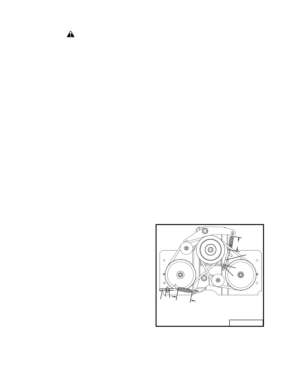
6. To adjust the belt tension, loosen the top
jam nut (item 2, Fig 6) on the J-bolt. Ad-
just the lower jam nut (item 3, Fig 6) so that
the spring coils are extended to a length of
2.75". Tighten the top jam nut against the
bracket.
7. Recheck spring tension length after unit has
run for ten (10) hours.
ADJUSTMENTS AND TROUBLESHOOTING
CAUTION
1
2
3
1
2
3
2.75"
2.75"
1. Idler Adjustment J-Bolt
2. Top Jam Nut
3. Lower Jam Nut
97068A
Fig. 6