15
Description of transmitter – case back
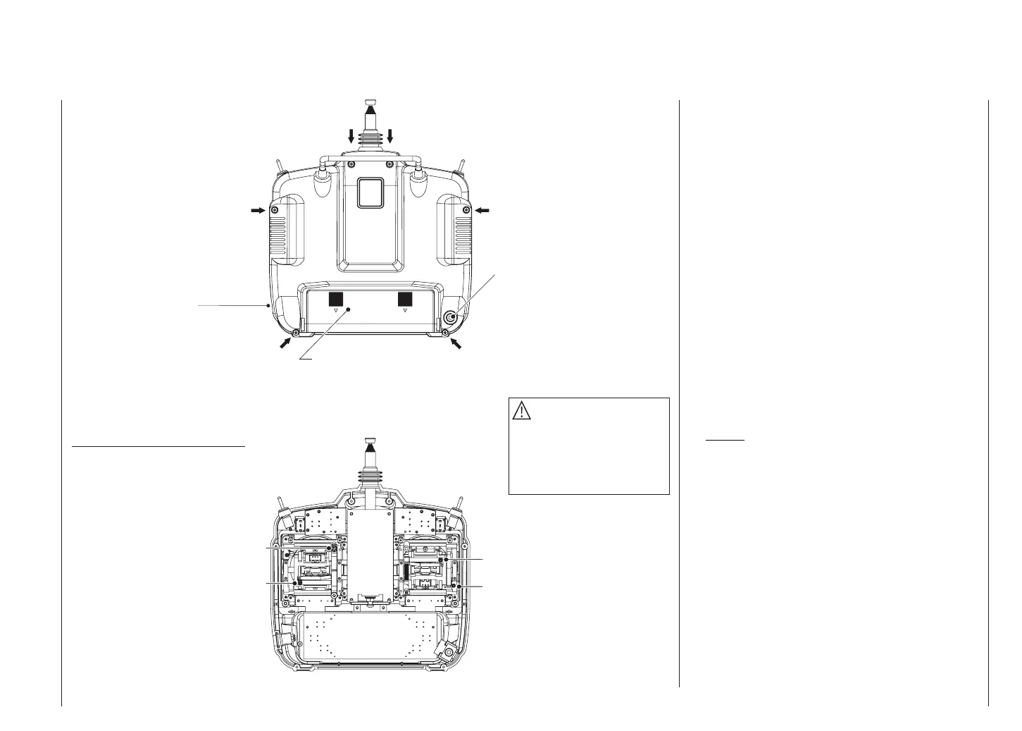
Transmitter case back
Left vertical
Right vertical
Right horizontal
Left horizontal
DSC socket for connection to fl ight simu-
lators, Trainer lead and Diagnosis (closed
loop) lead (see right-hand column)
DSC = Direct Servo Control
Case screw
Adjusting the centring spring force
Case screw
Battery compartment cover
Case screw
Case screw
Case screw
Do not touch the trans-
mitter circuit board!
Case screw
Caution
The battery lead is polarised,
i.e. it can only be plugged in
one way round. Don’t use force
when disconnecting the battery
connector!
DSC
Direct Servo Control
The original function of this socket was for “Direct Ser-
vo Control”, and that’s why the abbreviation is still in use.
However, it is now much more versatile than simply pro-
viding a means of controlling servos by cable. The DSC
socket is now also used as an interface for fl ight simula-
tors, and for connecting a Pupil transmitter to a Teacher
transmitter to form a Trainer (buddy box) system.
For the DSC connection to work you must check the
following:
1. Carry out any adjustments required in the appropria-
te menus:
If you are connecting the transmitter to a fl ight simu-
lator (for example), these settings are found in the
»Modulation« line of the »Base settings« menu –
“PPM” is usually required.
If you are connecting a Diagnosis lead (Order No.
4178.1), the modulation must be selected to suit the
receiver – see below.
See page 110 for information on setting up the mx-
16s transmitter to work as part of a Trainer system.
2. Always leave the transmitter’s On / Off switch in the
“OFF” position, for only in this position is the RF sec-
tion of the transmitter module switched off (no RF si-
gnal) even when the DSC lead is plugged in.
This is particularly important if you are using a Dia-
gnosis lead or a Trainer lead, otherwise you can still
cause interference to other pilots.
3. Connect the appropriate connecting lead to the DSC
socket on the back of the transmitter. This renders the
transmitter ready for use, circumventing the channel
section, and the LCD screen operates. At the same
time the letters “DSC” appear on the right-hand side
of the LCD screen, instead of the usual display of the
selected transmission channel.
4. Connect the other end of the connecting lead to the
desired apparatus, taking into account the operating
Do not touch the trans-
mitter circuit board!
Transmitter battery charge socket