33
Antenne
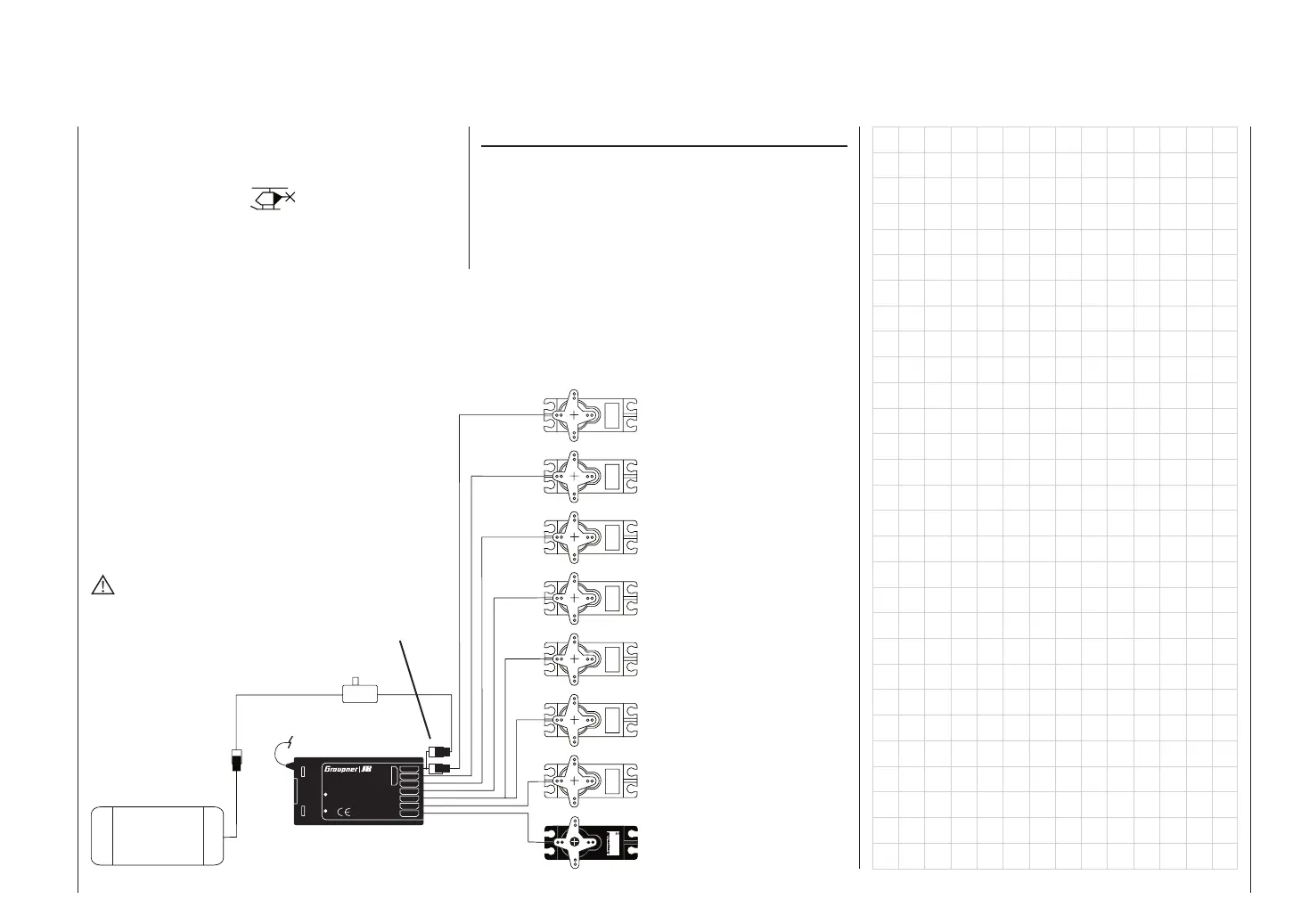
Switch harness
1 = Collective pitch or roll-axis
(2) or nick-axis (2) servo
2 = Roll-axis (1) servo
3 = Nick-axis (1) servo
5 = Free, or pitch-axis (2) servo
WARNING
Do not shorten the aerial!
4 = Tail rotor servo (gyro)
6 = Throttle servo (speed cont.)
7 = (Gyro gain)
8 = (Speed governor)
Model helicopters – Installation and connections
Receiver socket assignment for model helicopters
Servo
4,8 V
C 577
Best.-Nr. 4101
7
6
5
4
3
2
1
8/Batt.
PLL-Synthesizer-MICRO-SUPERHET
Best.-Nr.
7052
Kanal 60-282/182-191
für das 35MHz/35MHz-B-Band
SCAN LED
Made in Malaysia
R 1 6
FM
S C A N
! #
Receiver
battery
Installation notes
The servos must be connected to the receiver out-
puts in the order shown on this page:
Outputs not required are simply left vacant.
Please note the additional information on the follo-
wing pages.
Y-lead, Order No.
3936.11 or 3936.32
All menus which are relevant to model helicopters are
marked with a “helicopter” symbol in the “Program de-
scriptions”:
This means that you can easily skip irrelevant menus
when programming a model helicopter.
Receiver aerial