29
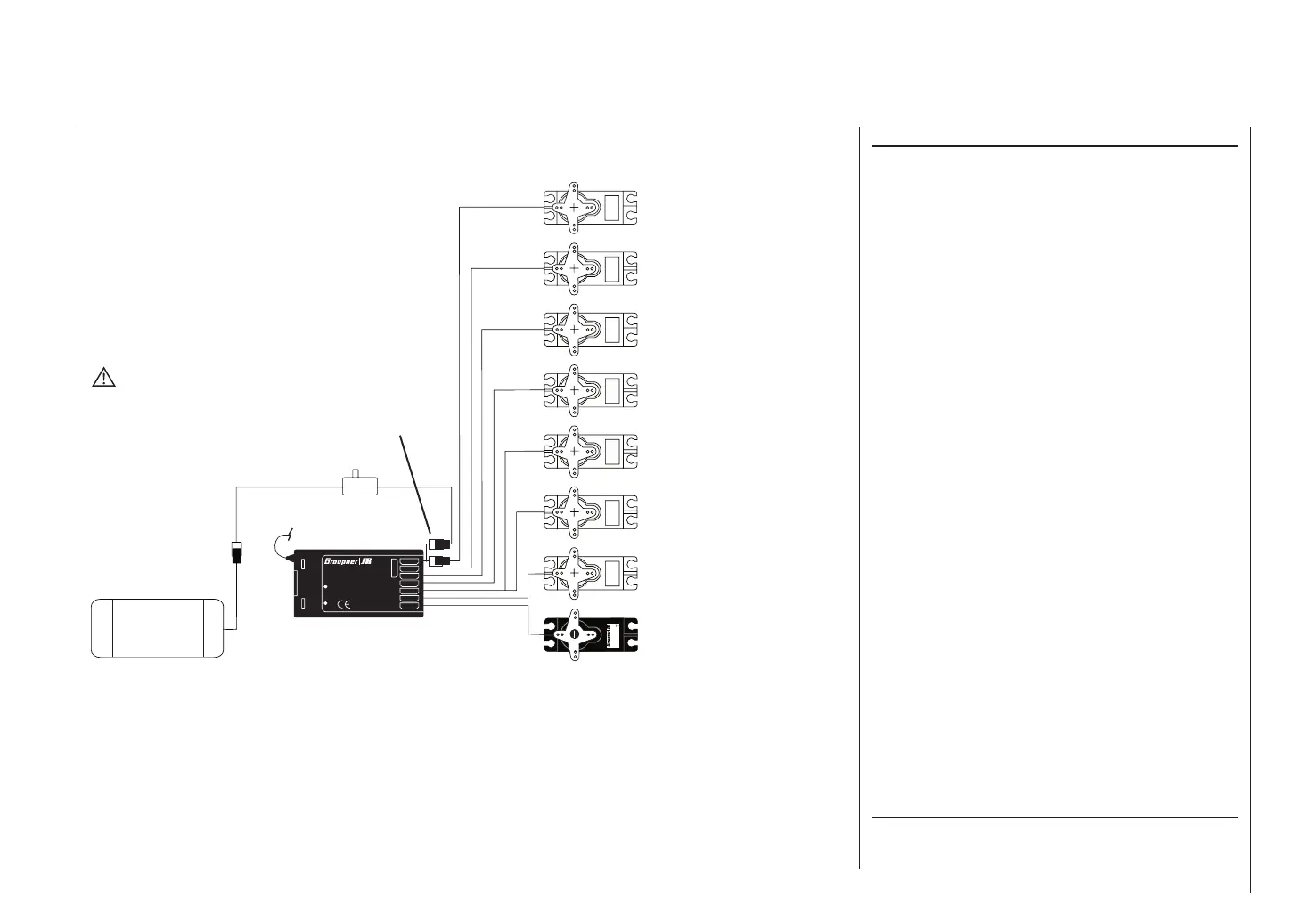
3 = Elevator / left V-tail
2 = Aileron / left aileron
8 = 2nd elevator / auxiliary func.
7 = Right fl ap / reserve
5 = Right aileron / reserve
4 = Rudder / right V-tail
1 = Throttle / brake
Installation notes
The servos must be connected to the receiver out-
puts in the following order:
Outputs not required are simply left vacant. Please note
the following points in particular:
• If you are using only one aileron servo, receiver out-
put 5 (right aileron) is left unused; it can also be used
for another purpose if you select “1 AIL” in the »Base
settings« menu.
• If you are using only one fl ap servo, receiver out-
put 7 (right fl ap) must be left unused, assuming that
you have selected “... 2 FL” in the »Base settings«
menu.
If you are using a Graupner transmitter to control a mo-
del fi tted with a PPM-FM receiving system made by ano-
ther manufacturer*, which was formerly fl own using a
different make of transmitter, e.g. when using the mx-
16s for Trainer mode operations, it may be necessary to
re-arrange the servo sequence at the receiver outputs
as shown in the diagram on the left. However, an alter-
native method is to use the »Receiver output« sub-
menu of the »Base settings« menu; see page 41. Dif-
ferent methods of installing servos and control linkages
may make it necessary to reverse the direction of rota-
tion of some servos when programming. In both cases
this is carried out in the »Servo settings« menu; see
page 48.
Please also read the information on the following
pages.
6 = Left fl ap / reserve
Fixed-wing models – Installation and connection
Receiver socket assignment for models with up to two ailerons and two fl aps, plus “normal” tail type, V-tail,
and two elevator servos (3 + 8)
*
GRAUPNER does not guarantee that GRAUPNER radio control sys-
tems will work correctly in conjunction with receiving systems and
radio control equipment made by other manufacturers.
Receiver aerial
WARNING
Do not shorten the aerial!
Switch harness
Receiver
battery
Y-lead, Order No.
3936.11 or 3936.32
Servo
4,8 V
C 577
Best.-Nr. 4101
7
6
5
4
3
2
1
8/Batt.
PLL-Synthesizer-MICRO-SUPERHET
Best.-Nr.
7052
Kanal 60-282/182-191
für das 35MHz/35MHz-B-Band
SCAN LED
Made in Malaysia
R 1 6
FM
S C A N
! #