67
Heli mixer – Model helicopter
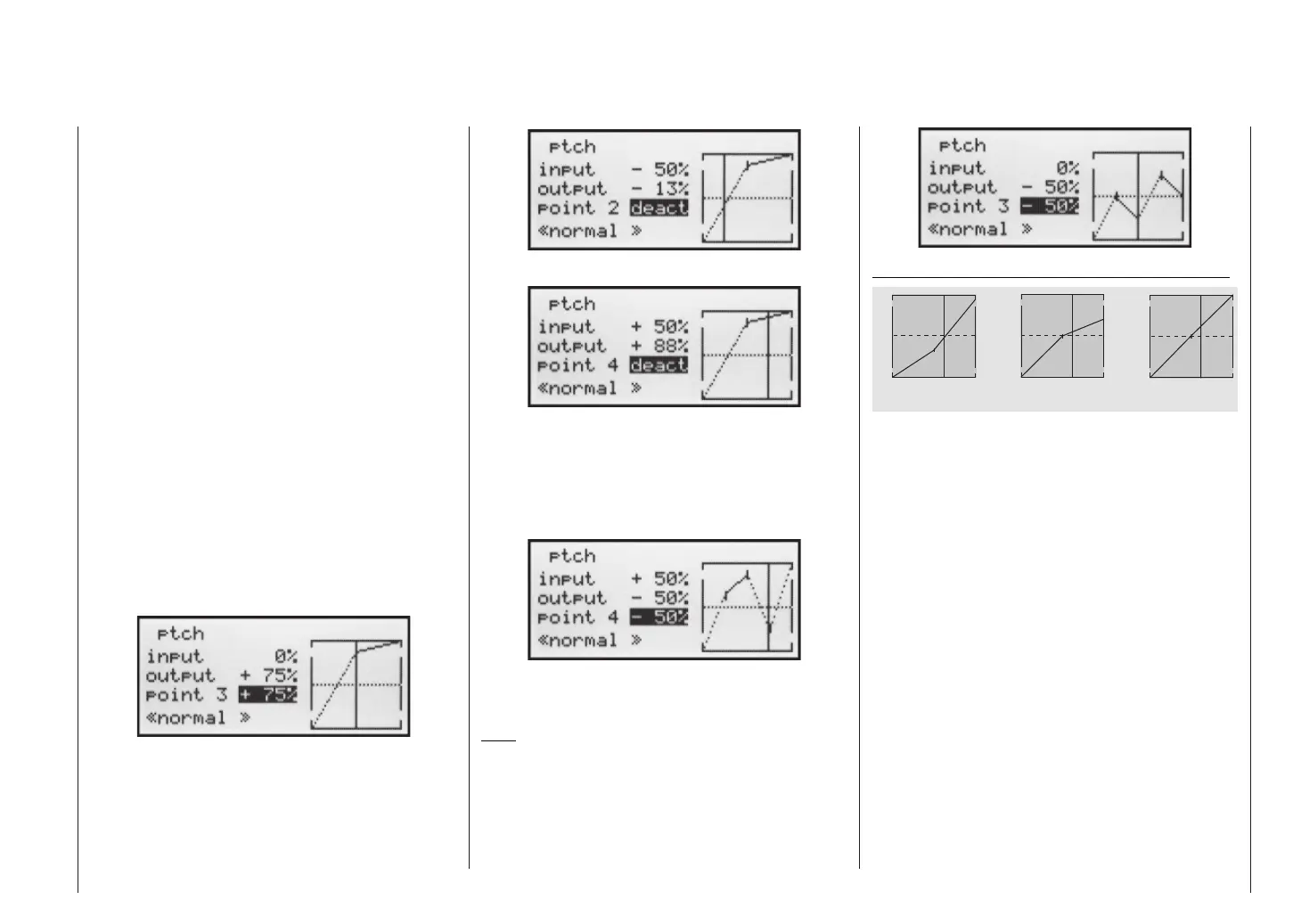
The throttle / collective pitch stick can now be used to
move the vertical line in the graph between the two end-
points “Point 1” and “Point 5”, and parallel to this the mo-
mentary position of the stick is displayed in numeric
form in the “Input” line (-100% to +100%).
The point where the vertical line crosses the curve is
termed the “Output”, and this point can be varied within
the range -125% and +125% at a maximum of fi ve refe-
rence points. This control signal, modifi ed in this way, af-
fects the collective pitch servos only. In the picture on
the left the stick is exactly at the 0% position at “Point 3”,
and also generates an output signal of 0% due to the li-
near characteristic of the graph.
By default only points “1” (collective pitch minimum at
-100%), “3” (hover point at 0%) and “5” (collective pitch
maximum at +100% travel) are active.
To set a point you use the associated stick to move the
vertical line to the point you wish to change. The num-
ber and current curve value of this point are displayed
in the bottom line in the left-hand half of the screen. The
right-hand rocker button can now be used to change the
current curve value in the highlighted fi eld to any value
within the range -125% to +125%, without affecting the
adjacent points.
In this example we have moved reference point “3” to
+75%.
However, points “2” and “4” can optionally be activated,
even though they are disabled by default. In the next ex-
ample we move point “2” to -50% …
… and point “4” to +50% …
This is accomplished using the stick to move the verti-
cal line to the appropriate area. As soon as the message
“inactive” appears in the highlighted value fi eld, you can
activate the associated point by pressing the right-hand
rocker button; it can then be adjusted in the same man-
ner as the other points …
… or reset to “inactive” by pressing the CLEAR button.
Points “1” and “5”, however, cannot be disabled.
Note:
The following illustration, and all the other pictures on
this page, show a control curve we prepared for illustrati-
on purposes only. Please note that the curve characteri-
stics by no means represent real collective pitch curves!
H o v e r
A e r o b a t i c s 3 D - F l y i n g
1 2 3 4 5
C o n t r o l T r a v e l
1 2 3 4 5
C o n t r
o l T r a v e l
1 2 3 4 5
C o n t r o l T r a v e l
O u t p u t
+ 1 0 0 %
- 1 0 0 %
O u t p u t
+ 1 0 0 %
- 1 0 0 %
O u t p u t
+ 1 0 0 %
- 1 0 0 %
Typical collective pitch curves for different fl ight phases: