78
vos may be employed for collective pitch control; the-
se will be connected to receiver outputs 1, 2, 3 and 5.
The mx-16s software links them together to provide
the functions collective pitch, roll and pitch-axis.
It is not advisable to mix one of the transmitter cont-
rols into these occupied channels using the free mi-
xers available outside the »Heli mixers« menu, as
you may inadvertently generate some extremely
complex and unwanted inter-actions. One of the few
exceptions to this rule is “Collective pitch trim via a
separate transmitter control”; see example 2 on page
80.
Important notes:
• It is essential to remember when dealing with serial
links that the travels of the individual mixers are cu-
mulative when multiple stick commands are made si-
multaneously, and there is then a danger that the ser-
vo concerned may strike its mechanical end-stops. If
you encounter this sort of problem, simply reduce the
servo travel in the »Servo settings« menu, and / or
reduce the mixer values.
• When an SPCM transmission link is in use, you may
encounter delay effects when a single transmitter
control operates a mixer combination which involve
multiple servos running in parallel. This does not con-
stitute a malfunction of the radio control system.
Mixer ratios and mixer neutral point
Now that we have explained the wide-ranging nature of
the mixer functions, we can move on to the method of
programming linear and non-linear mixer curves. The fol-
lowing section describes the procedure:
For each of the three available mixers the mixer cur-
ves are programmed on a second page of the screen
display. Select the number of the mixer you wish to ad-
just, and move to the symbol at bottom right of the
screen using the right-hand rocker button. A brief press
on SELECT now takes you to the graph page.
Setting up linear mixers
In the next section we will describe a typical practical
application, by defi ning a linear mixer curve intended to
solve the following problem:
We have a powered model with two fl ap servos connec-
ted to receiver outputs 6 and 7, which were program-
med in the »Base settings« menu. These control sur-
faces are to be employed as landing fl aps, i.e. when the
associated transmitter control is operated, they defl ect
down only. However, this fl ap movement requires an ele-
vator trim correction to counteract the resultant pitch trim
change.
In the »Control settings« menu, assign the rotary pro-
portional control CTRL 7 to input 6. The control assigned
to input 6 now controls the two servos connected to re-
ceiver outputs 6 and 7 in the standard way, operating as
simple wing fl aps.
»Control settings« menu
Note:
If you assign a transmitter control to input 7 and select
two fl ap servos, input 7 is automatically blocked to avoid
possible malfunctions.
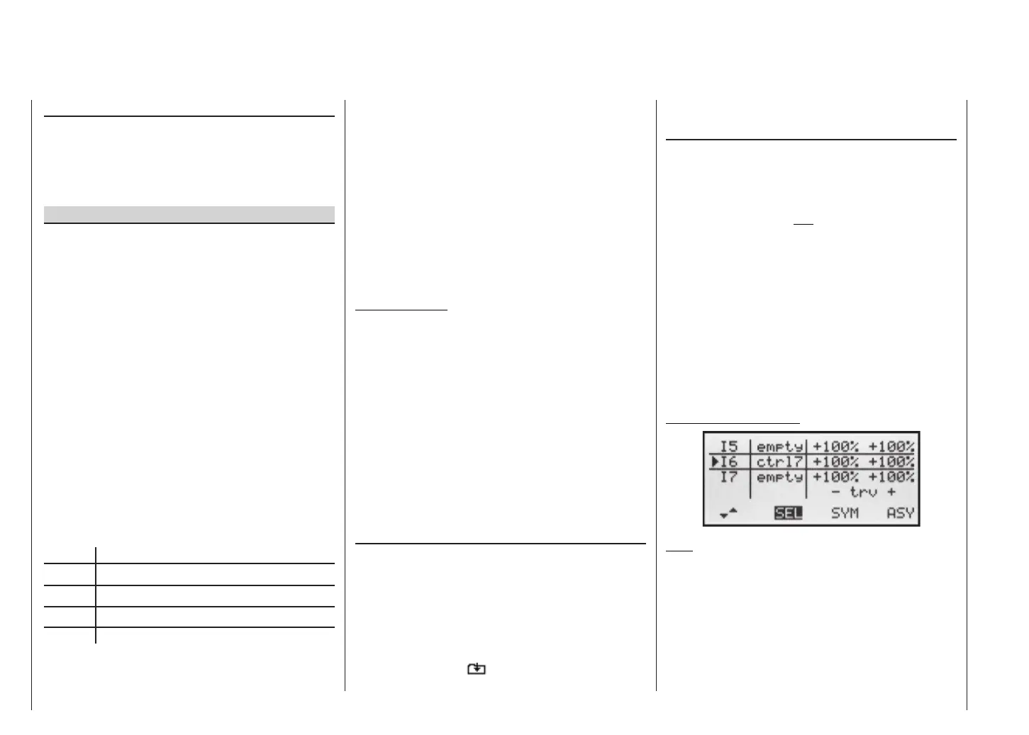
Rotate the rotary knob to its left-hand end-point, and ad-
just the landing fl ap linkages so that they are in the neu-
tral position at this slider setting. If you now turn the
knob to the right, the fl aps should defl ect down; if they
move up, you must reverse the direction of servo rota-
“Type” column (including the trim)
If you wish, and if you are using one of the primary con-
trol functions 1 ... 4 (sticks), you can set the trim value
of the digital trim lever to affect the mixer input. Use the
right-hand rocker button to select “tr” in the highlighted
fi eld for the mixer you are programming.
Additional special features of free mixers
If you set up a mixer whose input is the same as its out-
put, e.g. C1 C1, exotic results can be obtained in
conjunction with the option of switching a free mixer on
and off. You will fi nd one typical example of this on pa-
ges 92 … 93.
Before we come to setting mixer ratios, and conclude
with a few examples, we have to consider what happens
if a mixer input is allowed to act on the pre-set coupling
of aileron servos, fl ap servos or collective pitch servos:
• Fixed-wing models:
Depending on the number of wing servos set in the
“Aileron / Flap” line of the »Base settings« menu,
outputs 2 and 5 at the receiver are reserved for the
aileron servos, and outputs 6 and 7 for the two fl ap
servos, as special mixers are assigned to these func-
tions.
If mixer outputs are programmed to this type of cou-
pled function, you have to consider their effect, de-
pending on the control channel:
Mixer Effect
NN 2 Aileron effect
NN 5 Ailerons have fl ap function
NN 6 Flap effect
NN 7 Flaps have aileron function
• Model helicopters:
Depending on the type of helicopter, up to four ser-
Free mixers