6
4. Connection Diagram
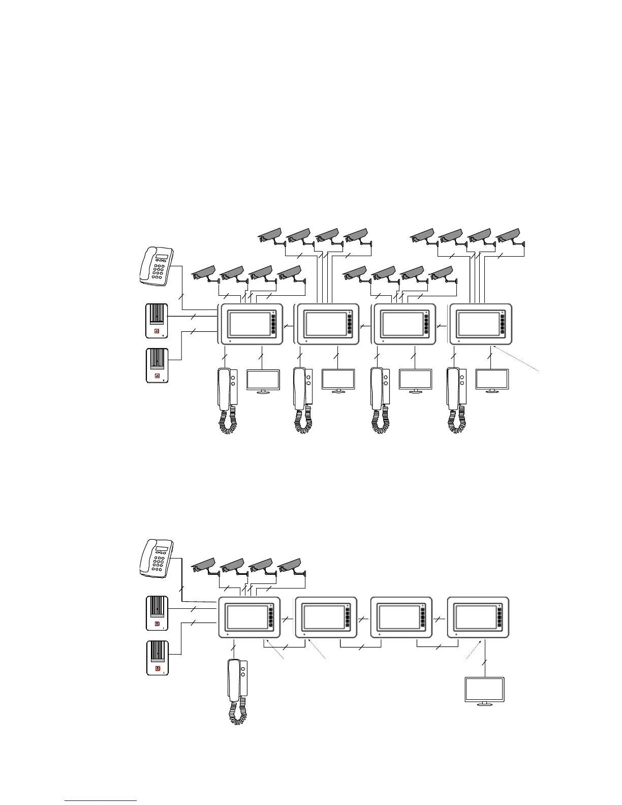
4.1 System Layout
There are two CCTV connection modes.
CCTV connection mode 1
Each monitor can connect to different CCTV, and can only monitor the directly
connected CCTV (Extensions ≤ 3).
2
4
2
4 24
2
4
2 2 2
2
2
2 2 2
2 2 2 2
2 2 2 2
4 4 4
CCTV_OUT
4
4
2
Master
Ext1 Ext2
Ext3
CCTV connection mode 2
Only master monitor can connect to CCTV, extensions get CCTV video from the master.
The extensions monitor CCTV by sending requests to the master. Only one monitor can
monitor CCTV at a time.
4
4
2 2
2
2
4 4 4
2 2 2
CCTV_OUT
CCTV_IN
4
2
Master
Ext1
Ext2
Ext3
2
CCTV_OUT
Master Ext.3 Ext.2 Ext.1
Master
Ext.1 Ext.2
Ext.3