GREE Photovoltaic Direct-driven Inverter Multi VRF Units
106
Step 1: Confirm entering the A2 refrigerant recovery operation settings. The master unit is displayed
as follows:
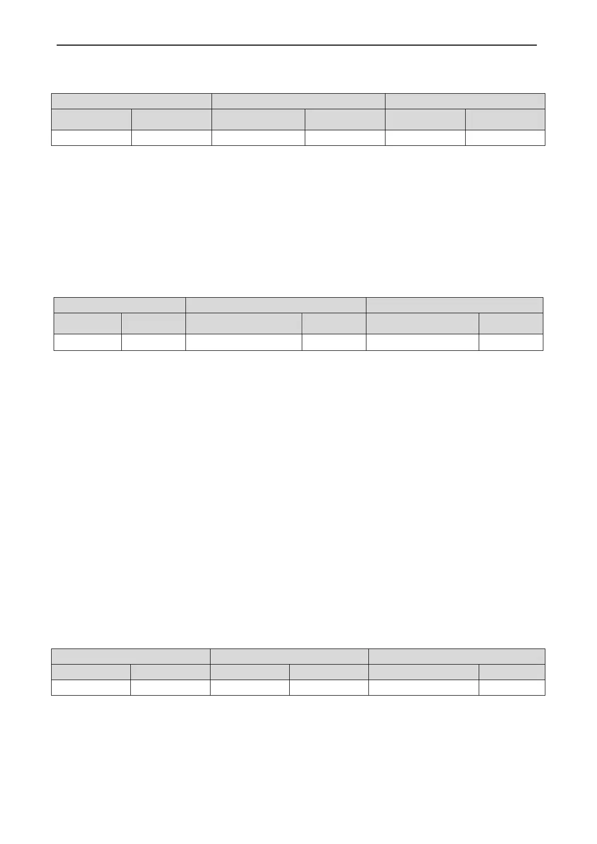
LED1 LED2 LED3
Function Code Display Mode
Refrigerant
Recovery Code
Display Mode Current Status Display Mode
A2 On 01 Blinking 00 Blinking
Step 2: The default setting is “01”. Select "01" or "02" by pressing "SW1 (UP)" or "SW2 (DOWN)".
Press "SW7" to confirm selecting the mode.
On the master unit, press "SW6" to return to the upper level.
If no button operations are performed on the master unit for five minutes, the function setting
automatically quits and the unit restores the current status.
Indoor unit pipeline refrigerant recovery
Step 3: Select "01” as in step 2 to enter IDU refrigerant recovery. Digital LEDs and status LEDs of all
basic modules are displayed as follows:
LED1 LED2 LED3
Refrigerant Recovery
Code
Current Status
A2 On 01 On [Module low-pressure Ps] On
LED3 shows the low-pressure value of a module. If the value is negative, LED3 circularly displays
the negative code "nE” and the numeric value every one second. For example, for -30
°
C, LED3
alternately displays “nE” for one second and then “30” for another second.
Step 4: Close liquid-tube stop valves of all basic modules of the ODU. When the low-pressure value
displayed on LED3 continually blinks, quickly close air-tube stop valves of all basic modules and then
press "SW7" on the master unit to confirm completing refrigerant recovery or power off the entire unit.
If no operations are performed after the low-pressure value displayed on LED3 continually blinks for
three minutes, the entire unit will be forcibly stopped.
On the master unit, press "SW6" to return to the upper level for restoring the standby status of the
entire unit (press "SW6" in setting status to return to the upper level; press "SW6" after settings are
completed to restore the normal operating status of the unit).
NOTICE!
Another startup is not allowed within 10 minutes after refrigerant recovery.
Basic module refrigerant recovery
Step 3: Set the basic module requiring refrigerant recovery to module emergency operation status
and close the liquid-tube stop valve of the emergency status module. Select "02” as in step 2 to enter
basic module refrigerant recovery. The display is as follows:
LED1 LED2 LED3
Function Code Display Mode Current Progress Display Mode Current Status Display Mode
A2 On 02 On Module high-pressure On
LED3 shows the high-pressure value of the module.
Step 4: When the high-pressure value displayed on LED3 continually blinks (displayed as 0
°
C if the
high pressure is less than 0
°
C), quickly close the air-tube stop valve of the emergency module and then
press "SW7" on the master unit to confirm completing refrigerant recovery or power off the entire unit.

 Loading...
