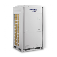
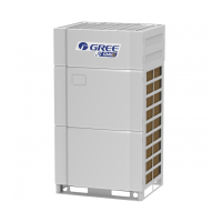
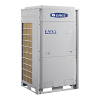
GREE Photovoltaic Direct-driven Inverter Multi VRF Units
8
3.2 Names and Main Functions of Components
No Name Main Function
1 Compressor
Adjusts its own rotational speed based on the actual requirement of the
system to implement capacity control.
2 Compressor heat tape
Maintains a proper oil temperature in the compressor when the
compressor is in standby status, ensuring the reliability during compressor
3
Compressor casing-top temperature
Detects a compressor's exhaust gas temperature for compressor control
4
Exhaust pipe temperature sensor of
Detects a compressor's exhaust gas temperature for compressor control
5 High-pressure circuit breaker
Protects a compressor by sending feedback signal to stop the system
when the compressor's discharge temperature exceeds the operating
value of high-pressure circuit breaker.
6 Oil extractor Separates the gas and oil in the system to ensure compressor reliability.
7 Oil balance device
Equalizes the oil for all modules in the case of excess oil in the current
module when multiple modules are arranged in parallel, thus ensuring the
8 Heat tape of oil balance device
Maintains a proper oil temperature in the compressor when the
compressor is in standby status, ensuring the reliability of compressor
9 One-way valve
Prevents high-pressure gas from entering the compressor and fast
balances the suction pressure and discharge pressure in a compressor.
10 High-pressure sensor
Detects the high pressure value in the system in real time mode for
compressor protection and other control functions.
11 Four-way valve
Used for the switching between the cooling and heating functions of
Used for outdoor heat exchange.
Strengthens heat exchanging.
Defrosting temperature sensor
Used for defrosting detection.
Electronic expansion valve for heating
Controls refrigerant adjustment in heating mode.
Controls refrigerant flow direction.
17 Subcooler electronic expansion valve
Controls the degree of subcooling of tube refrigerant when the system is
running in cooling mode, and reduces the capacity loss on pipes.
18 Subcooler Controls the degree of subcooling of tube.
19
Liquid outlet temperature sensor of
Detects tube temperature.
20
Inlet temperature sensor of gas-liquid
Detects the inlet temperature of gas-liquid separator to prevent the system
from running when the refrigerant flows back to the compressor.
21
Gas outlet temperature sensor of
Detects gas temperature of subcooler.
22 Low-pressure sensor Detects system low pressure to avoid extra-low operating pressure.
23 Gas-liquid separator
Separate gas and liquid to prevent the system from running when the
refrigerant flows back to the compressor.
24
Outlet temperature sensor of gas-liquid
Detects internal status of gas-liquid separator to further control the
compressor suction performance.
Used for oil balance control among modules.
Used for oil balance control among modules and avoid reverse flow of oil.
27 Unloading valve Avoids over-high pressure caused by pipeline blind spot.
28 Oil balance valve 2 Used for oil balance control among modules.
29 Filter Prevents impurities from entering components and parts.
30 Capillary tube Supports flow regulating and pressure reduction.

 Loading...


