GREE Photovoltaic Direct-driven Inverter Multi VRF Units
285
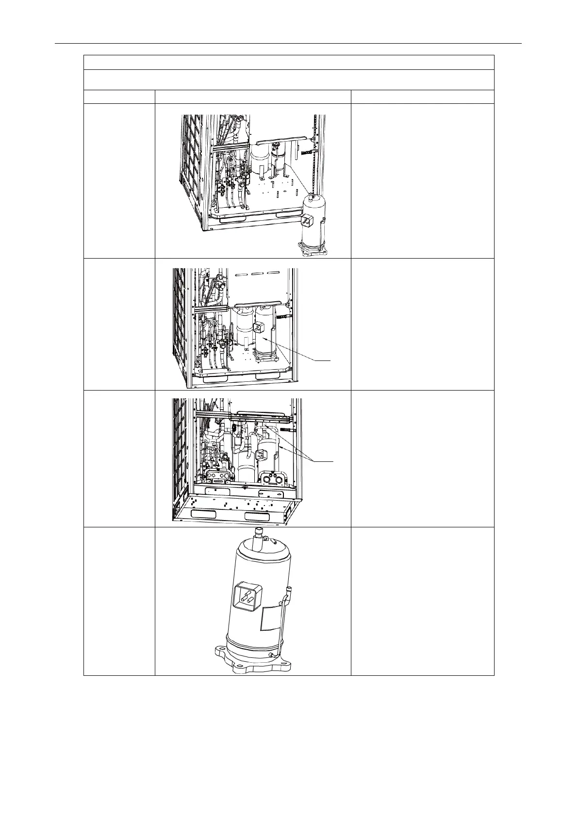
Removal procedure of compressor
Note: Before removing the compressor, make sure no refrigerant is inside the pipeline and power has
been disconnected.
.
compressor.
●Remove the compressor from
the chassis.
.
Install a new
compressor on
the chassis.
●Put the new compressor in a
proper position;
●Use a wrench to screw the nuts
on the compressor;
● The compressor should not be
installed upside down.
.
discharge pipes
of the
compressor to
the pipeline
system.
●Heat the suction and discharge
p
ipes by acetylene welding and
then install the pipes;
● During welding, charge nitrogen
into the pipes. The pressure
should be controlled within
0.5±0.1kgf/cm
2
(relative
pressure);
●Avoid nearby materials from
being burnt during welding.
.
Connect the
power cord of
compressor,
and install the
electric heating
belt, top
temperature
discharge
temperature
sensor.
●Put the power cord in a proper
position according to the order of
disassembly;
● Use a screwdriver to screw the
power cord;
● Install the electric heating belt,
top temperature sensor, and
discharge temperature sensor;
● Put the sound-
back to position.

 Loading...
