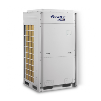
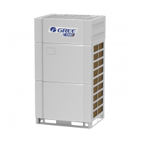
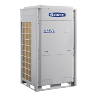
GREE Photovoltaic Direct-driven Inverter Multi VRF Units
290
Removal procedure of electronic expansion valve
Note: Before removing the electronic expansion valve, make sure no refrigerant is inside the pipeline
and power has been disconnected.
install
panels.
connection wires;
●If no problem is found, hook
the front panels and tighten
the screws.
3.3.4 Disassembly and Assembly of Oil Separator
Removal procesure of oil separator
Note: Before removing the oil separator, make sure no refrigerant is inside the pipeline and power has
been disconnected.
Loosen the
hooks at the
bottom of the
electric box and
the screws
lower front panels;
●Loosen the hook
bottom of the electric box;
● Use a screwdriver to
unscrew the electric box.
electric box.
●Disconnect internal and
external connection wires of
the electric box;
●Protect the internal parts
during the disassembly.
the oil separator.
●Use a screwdriver to loosen
the screws securing the oil
separator;
●Loosen the electric heating
belt on oil separator;
●Loosen the 4 joints on oil
separator by welding and
then remove the connection
pipes. Note: Av
parts from being burnt during

 Loading...


