GREE Photovoltaic Direct-driven Inverter Multi VRF Units
293
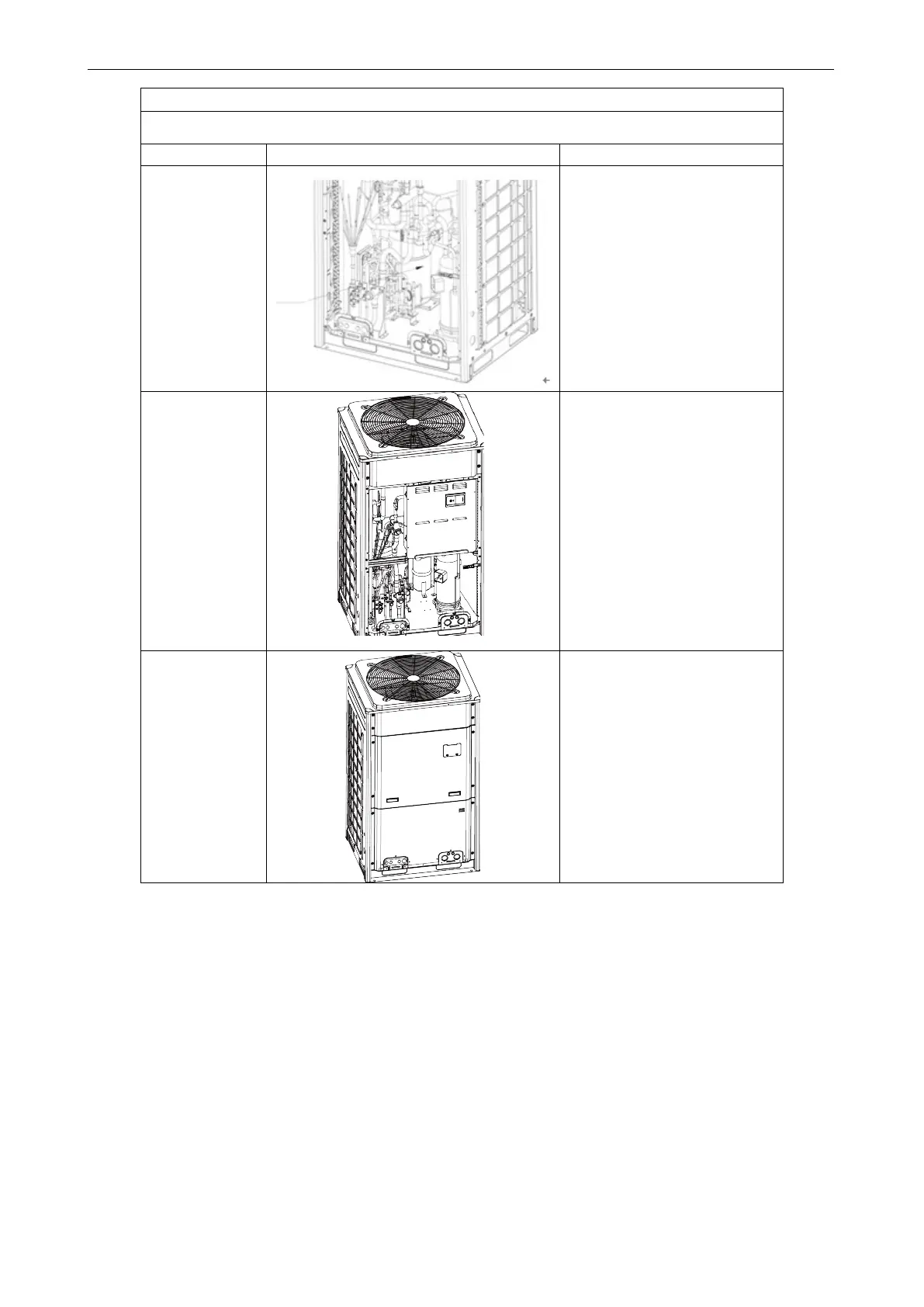
Removal procedure of gas liquid separator
Note: Before removing the gas liquid separator, make sure no refrigerant is inside the pipeline and
power has been disconnected.
5. Install a new
gas liquid
separator.
●Put the gas liquid separator
based on the positi
suction and discharge pipes and
weld the pipes with the gas liquid
separator;
●During welding, charge nitrogen
into the pipes. The pressure
should be controlled within
0.5±0.1kgf/cm
2
(relative
pressure). Note: Avoid nearby
parts from being burnt during
welding;
●Screw the gas liquid separator.
the electric box.
●Put the electric box back to the
original position and screw it;
●Connect wires same as the
original.
7. Check and
install the front
panels.
connection wires;
●If no problem is found, hook the
front panels and tighten the
screws.

 Loading...
