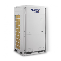
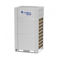
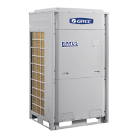
GREE Photovoltaic Direct-driven Inverter Multi VRF Units
66
7.2.2 Requirements on Power Cable Configuration
Configure a circuit breaker to each unit for short circuit and overload protection. In addition,
configure a general circuit breaker to both the indoor and ODUs to switch on or switch off the general
power of the IDU or ODU.
(1) External Connection for Individual Units
AC
DC POWER
AC
POWER
AC POWER
3
3
L1
L2
L3
IDU 1
L1
L2
L3
D1
D2 H1 H2
IDU n
L1
L2
L3
D1
D2
H1 H2
IDU 2
L1
L2
D1 D2
H1
H2
G
G
G
G
G
G
QF
QF
QF
......
master module
Wired controller
Wire
(resistance-matching)
COMMUNICATION
COMMUNICATION
COMMUNICATION
POWER
POWER
POWER
Communication cord
Power cord
Power cord
G
G
Wired controller
Wired controller
QF
QF
QF
PV1+ PV1-
PV2+
PV2-
ODU 1
PV Array
Power cord
Remote monitor
D1
D2 G1
G2
COMMUNICATION
Indoor Unit ground Lines are required for preventing electrical shock accident during current
leakage, Communication disorder by noise effect and motor current leakage (without connection to
pipe).
Don't install an individual switch or electrical outlet to disconnect each of indoor unit separately
from the power supply.
Install the main switch that can interrupt all the power sources in an integrated manner because
this system consists of the equipment utilizing the multiple power sources.
If there exists the possibility of reversed phase, lose phase, momentary blackout or the power
goes on and off while the product is operating, attach a reversed phase protection circuit locally.Running
the product in reversed phase may break the compressor and other parts.

 Loading...


