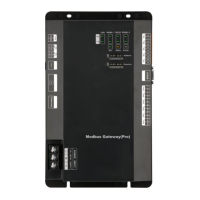
Modbus Gateway(Pro) Technical Service Manual
9
3.Device Installation
3.1 Product Dimension and Installation Space of Electric Control
Cabinet
3.1.1 Product Dimension
1 65432 7 8
0
1
Function
1
0
is the position of DIP
Without matched resistance
With matched resistance
8
8
L × W × H:296×177×56(mm)
3.1.2 Installation Space of Electric Control Cabinet
Modbus Gateway(Pro) shall be installed in the electric control cabinet. The front side of
gateway shall be hung upwards and secured by four screws. Required installation space is shown
as below (only for reference).
CAUTION.
① It is suggested to install Modbus Gateway(Pro) near the air conditioner to reduce the
communication distance between Modbus Gateway(Pro) and air conditioner. As the
communication distance between Modbus Gateway(Pro) and air conditioner shall be within 500m
(please refer to 3.2 Communication Connection for more details). Communication distance
between Modbus Gateway(Pro) and BMS system can be expanded through 485 repeater.
② The power cord and communication cable of Modbus Gateway(Pro) shall be wired
separately. Otherwise, Modbus Gateway(Pro) may have errors! Fine dash line in the figure is the
communication cable and thick dash line in the figure is the heavy current wire. The wiring in the
figure is only for reference.
③ Before making central control cabinet, please design according to the quantity and
Secure
it by four
screws
296mm
177mm
With the front side
hung upwards
120mm 120mm 120mm
50mm
Wire groove
120mm 120mm
98.5mm
Electric control
cabinet
120mm
Wire groove

 Loading...