Modbus Gateway(Pro) Technical Service Manual
17
This device does not use this LED indicator.
When power supply of Modbus Gateway(Pro) is normal, it
will be always on..
When Modbus Gateway(Pro) works normally, it will blink.
This device doesn’t use this LED indicator.
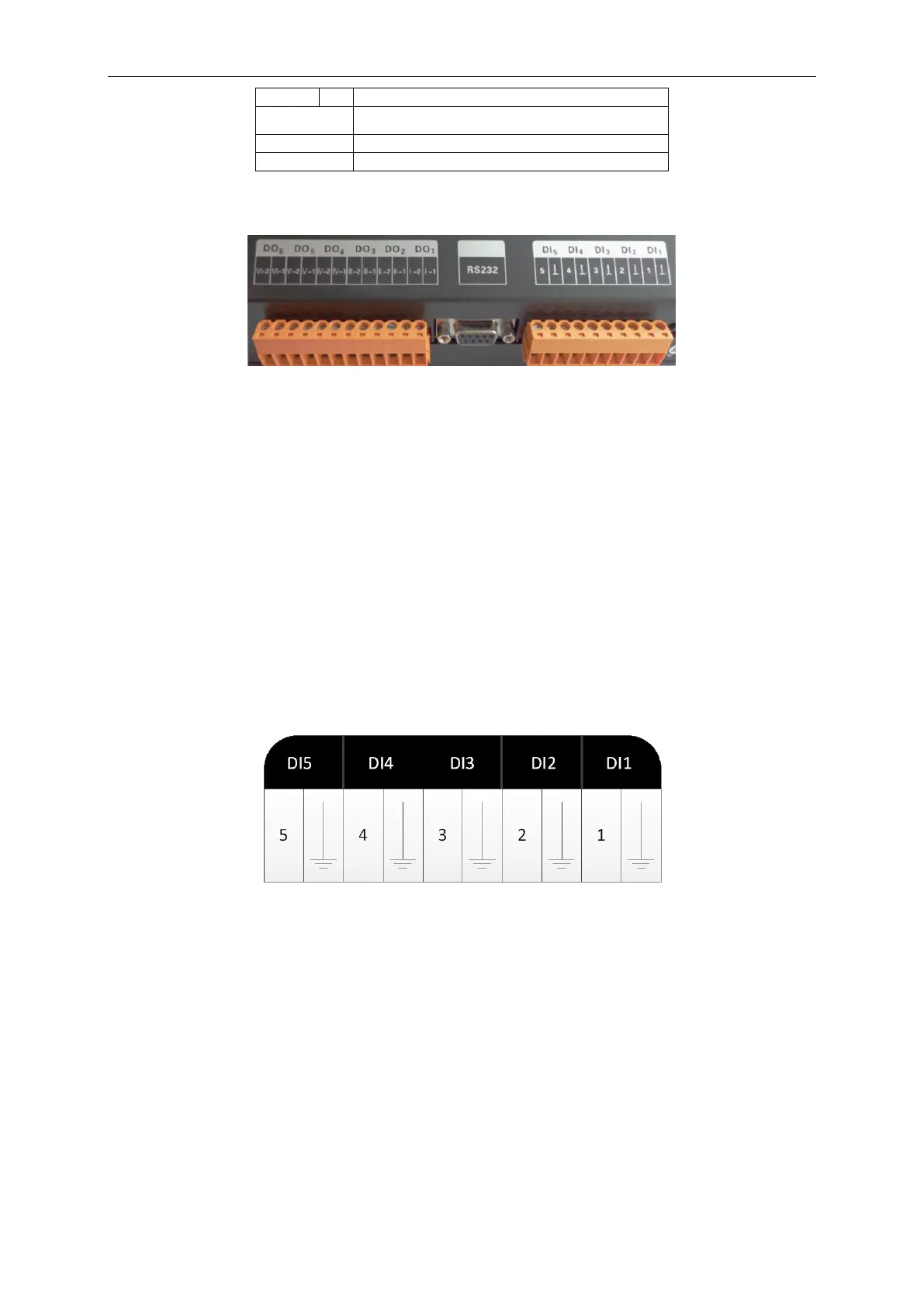
1.3 DI/DO
This gateway supports 5 DIs(digital inputs) and 5 DOs(digital outputs); DO6 is reserved.
DI1...DI5
Digital inputs: 0/1 digital signals(binary system), applicable for those with power supply
DI1: in CAN2 network, fire alarm signal, connect “1” to the power of 12V, input fire alarm
signal “1” in DI 1 port, then Modbus gateway(Pro) will give out control, all units stop
operation immediately;disconnect “1” or connect to “0”, input signal “0” in DI 1
port,resume operation of all ODUs.
In CAN1 network, fire alarm signal, connect “1” to the power of 12V, input fire alarm
signal “1” in DI 1 port, then Modbus gateway(Pro) will give out control, all units stop
operation immediately;disconnect “1” or connect to “0”, input signal “0” in DI 1
port,resume operation of IDUs manually.
DI2...DI5: Defined by the user.
DO1...DO5 digital outputs: Relay output, normally-open contact
Max admissible power: 250VAC, 3A; 30VDC, 3A
Example: write “1” into DO5 of Modbus protocol and the two contacts of DO5 relay will be
closed; write “0” into DO5 of Modbus protocol and the two contacts of DO5 relay will
be cut off.

 Loading...


