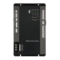
Modbus Gateway(Pro) Technical Service Manual
10
arrangement way of Modbus Gateway(Pro) and the placement status.
④ Each Modbus Gateway(Pro) shall have independent power supply. Therefore, sufficient
220V AC socket for power supply must be installed in the central control cabinet.
⑤ Keep the distance between communication cable and heavy current wire for more than
15cm and do not bind them together. If they cannot be kept away from 15cm, please apply
shielding steel pipe to avoid communication error caused by electromagnetic interference.
⑥ The control cabinet shall be installed indoors to avoid direct sunlight and rain. It shall be
locked to keep it away from the reach of people other than management personnel.
3.2 Communication Connection
Communication system of Modbus Gateway(Pro) includes:
(1)Communication between Modbus Gateway(Pro) and BMS;
(2)Communication between Modbus Gateway(Pro) and air conditioner.
3.2.1 Material Selection of Communication Cable
Communication between
Modbus Gateway(Pro)
and BMS
Light/Ordinary PVC
sheathed twisted pair
copper wire(60227
IEC52/60227 IEC53)
When communication
distance exceeds
800m, photoelectric
isolation repeater shall
be added
Communication between
Modbus Gateway(Pro)
and air conditioner
Light/Ordinary PVC
sheathed twisted pair
copper wire(60227
IEC52/60227 IEC53)
The length of
communication cable
shall not exceed 500m
3.2.2 Communication Connection Way
CAUTION! All communication cables of Modbus Gateway(Pro) must be connected in series
instead of in star mode.
(1)Communicaiton connection between Modbus and BMS;

 Loading...