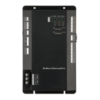
Modbus Gateway(Pro) Technical Service Manual
22
Chapter Ⅲ Maintenance
1.Troubleshooting of BMS System
BMS system displays communication error
warning according to the provided protocol;
the operation status of some or all units
cannot be displayed and cannot be
controlled
Communication cable is not
twisted-pair communication
cable
Change to twisted-pair
communication cable
Modbus Gateway(Pro) is broken
Replace Modbus Gateway(Pro)
There is breakage in the
communication cable
Communication cable is
short-circuited
Repair the short-circuited part
Twisted-pair cable is too closed
to power cord (less than 15cm),
which leads to communication
error caused by big interference
Wire the communication cable
and power cord separately; if
they cannot be kept away from
15cm, please apply shielding
steel pipe
Wrong connection of
communication interface
Connect communication
interface according to the
instructions in this manual
The circuit is normal after checking, but all
units or some units don’t have information
display and the software still has
communication error
Haven’t de-energized and then
energized the outdoor unit after
replacing chip or reset DIP
switch
Matched resistance hasn’t been
connected
Set the matched resistance
correctly
The serial port that
communication software used
doesn’t match with the serial port
no. that computer connected
Replace the serial port or
change the serial port setting of
the software
Unit address added in the
software doesn’t match with the
address of actual unit
Change unit address setting of
software
The unit hasn’t been energized
Chip hasn’t been inserted in the
outdoor unit or indoor unit, or the
inserting direction of chip is
wrong
Reinsert the chip according to
the indentation direction on the
PCB and then re-energize it
Unit address is wrong or
repeated
Change the wrong unit address
setting
Circuit, device and engineering installation
are normal, but there still is communication
error in the software
Use the wrong display or
controller which doesn’t match
with actual unit
Check the controller and wired
controller models of current
unit; contact after-sales service
center if the models are wrong
Circuit and other device layer are normal,
while only a certain device layer doesn’t
have information display completely
Relay shall be installed. If relay is
installed, the wire connection of
relay may be wrong
Install the relay correctly

 Loading...