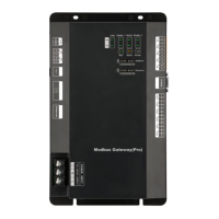
Modbus Gateway(Pro) Technical Service Manual
6
Converter
equipped with
power supply
Wire A of RS485 connects with R+ of 485
wiring terminal, wire B connects with R-.
RS232 interface connects with RS232 of
computer.
For more details,
please refer to the
user’s manual
It is always bright when power supply is put
through
For more details,
please refer to the
user’s manual
TX and RX lights are blinking when
communication is normal
For more details,
please refer to the
user’s manual
2.3.4 Product Dimension
2.3.5 Notices for Installation and Operation
Warning! It must be installed indoors, to avoid impact, direct sunlight or rain. It is suggested
to put it in the monitoring room with computer.
Warning! The devices provided by the manufacturer must be applied. Do not apply the
products of other models or brands.
Warning! Independent power supply shall be used. Sufficient 220V AC socket must be
installed to supply power.
2.4 Introduction of Photoelectric Isolation Repeater
2.4.1 Functions
Functions of photoelectric isolation repeater
1)When the distance of the whole communication network node exceeds 800m, it shall be
used to ensure the integrality of signal and avoid attenuation of signal in long communication
distance.
2)Currently, normal photoelectric isolation repeater can support the integrality of
communication signal of 32 nodes. When communication node quantity in the network exceeds 32
nodes, communication signal will not be integral. To ensure reliable transmission of signal,

 Loading...