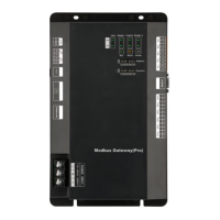
Modbus Gateway(Pro) Technical Service Manual
16
1.2 LED Display
LED indicators shown in the above figure are divided into two parts: status indicators
(operation, alarm, power) and communication indicators(CAN, RS485, RS232). Operation status
of each indicator is shown in the following table.
When the data from the equipment (e.g. air conditioner)
connected with Modbus Gateway(Pro) is received, it will
flash.
When the data is transferred to the equipment (e.g. air
conditioner) connected with Modbus Gateway(Pro), it will
flash.
When the data from the Modbus bus is received, it will
flash.
When the data is transferred to the Modbus bus, it will
flash.
This device does not use this LED indicator.
This device does not use this LED indicator.
This device does not use this LED indicator.
…
Master
control unit
of ODU
system 1
Set as with
matched
resistance
Set as
without
matched
resistance
Master
control unit
of ODU
system 2
Master
control unit
of ODU
system n
CAN2 bus
Set as
without
matched
resistance
Set as with
matched
resistance
…
Master
control unit
of ODU
system 1
Set as with
matched
resistance
Set as
without
matched
resistance
Master
control unit
of ODU
system 2
Master
control unit
of ODU
system n
CAN2 bus
Set as
without
matched
resistance
Set as with
matched
resistance

 Loading...