Modbus Gateway(Pro) Technical Service Manual
15
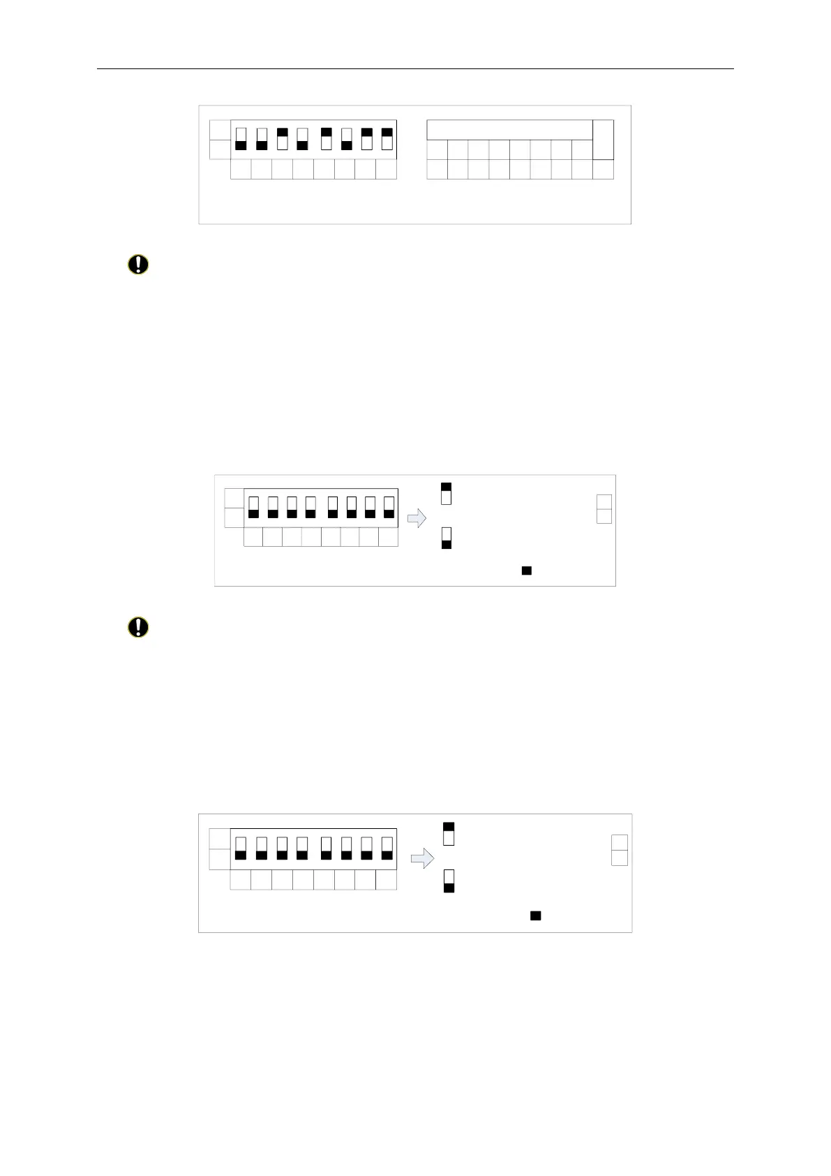
Setting method of address 43 is shown as below:
1 65432 7 8
0
1
Address
Address
1 1 0 1 0010 43
1 2 3
4 5 6 7 8
value
DIP form
3)The Seventh Switch of Function DIP Switch-Setting of Modbus Bus Matched Resistance
CAUTION! Master outdoor unit or gateway of the system which is at the end of Modbus
bus must be set as with the matched resistance, otherwise communication will be abnormal!
Modbus bus: Detailed meaning please refer to topology introduction.
The seventh switch of function DIP switch is used for setting the Modbus bus matched
resistance of this gateway.
If the gateway is at the end of Modbus bus, the gateway shall be set as with the matched
resistance, which means set the seventh DIP switch to 0;
If the gateway is not at the end of Modbus bus, the gateway shall be set as without the
matched resistance, which means set this DIP switch to 1.
DIP switch of matched resistance is shown as below:
1 65432 7 8
0
1
Function
1
0
is the position of DIP
Without matched resistance
With matched resistance
7
7
4)The Eighth Switch of Function DIP Switch – Setting of CAN2 Bus Matched Resistance
CAUTION! Master outdoor unit or gateway of the system which is at the end of CAN2 bus
must be set as with the matched resistance, otherwise communication will be abnormal!
※
CAN2 bus: Detailed meaning please refer to topology introduction.
The eighth switch of function DIP switch is used for setting the CAN2 bus matched resistance
of this gateway.
If the gateway is at the end of CAN2 bus, the gateway shall be set as with the matched
resistance, which means set the eighth DIP switch to 0;
If the gateway is not at the end of CAN2 bus, the gateway shall be set as without the matched
resistance, which means set the eighth DIP switch to 1.
1 65432 7 8
0
1
Function
1
0
is the position of DIP
Without matched resistance
With matched resistance
8
8

 Loading...


