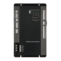
Modbus Gateway(Pro) Technical Service Manual
12
1 2
①
②
BMS
ONON
1 2
SA8
ONON
…
…
④
⑤
Modbus Gateway(Pro) 1
Master
ODU
Slave
ODU
Modbus Gateway(Pro) 2
Slave
ODU
Master
ODU
SA8
③
④
⑤
3.2.3 Communication Connection Steps
(1)Communication wire connection between Modbus Gateway(Pro) and BMS:
Step 1: Confirm the first Modbus Gateway(Pro) (Modbus Gateway(Pro)1 as shown in the figure)
that needs to be connected to BMS. Connect the R+ and R- port of RS485-1 communication
interface of this gateway and the BMS with communication cable, as shown in step
①
in the
figure.
Step 2: Connect the R+ and R- port of RS485-1 communication interface of Modbus Gateway(Pr
o)(Modbus Gateway(Pro)1) and the R+ and R- port of RS485-1 communication interface of the se
cond Modbus Gateway(Pro)(Modbus Gateway(Pro)2 as shown in the figure) with communication
cable, as shown in step
②
in the figure. If several Modbus Gateways(Pro) shall be connected,
please connect them in this way.
(2)Communication wire connection between Modbus Gateway(Pro) and air conditioner:
Step 1: Confirm the master ODU that each Modbus Gateway(Pro) shall be connected. Please
refer to “3.2.2(2) Communicaiton connection between Modbus Gateway(Pro) and air
conditioner”and adopt series connection, as shown in step
④
in the figure.

 Loading...