Super Free Match
Service Manual
INSTALLATION
107
7.6 Electrical Wiring Work for Outdoor Unit
1) Knock the holes in the plate of the chosen direction with the hammer.
2) Place the rubber ring on the knockout hole.
3) Let the power cable and transmission line go through the knockout hole.
4) Connect the power cable of the outdoor unit to the L1, L2 terminals with the sign of the XT1 and as well
as the ground screw.
5) Connect the transmission line of the outdoor unit to the N(1), 2 terminals with the sign of the XT2.
6) Fix the power cable and transmission line firmly by cable fixing clip.
7) Screw the coping plate, front side plate, right connection board, front connection board back.
8) Cover the through-holes with sealing materials to prevent the water, dust or small animals going into the
outdoor unit.
Caution!
The transmission line and the power cable must be separated and separated with an interval of at least
2cm; otherwise it may be result in communication problem.
In order to protect the power cable and transmission line from damaging by the hole, the rubber ring
must be placed on the hole. Otherwise, it may cause electrical shock or fire etc.
The power wire and transmission line must be more than one meter away from televisions or radios
which can emit electromagnetic waves to prevent image interference or noise. Otherwise, the unit
maybe cannot work.
Confirm the each cable connected to the terminal screw is exactly and securely after finishing the
electric work.
Fix each ground wire separately with the ground screw.
If the connecting wire is connected to the terminal incorrectly, the unit will not work normally.
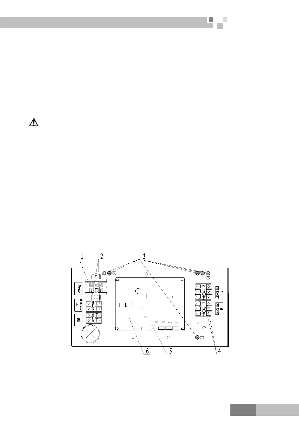
7.7 Electrical Wiring Work for BU Module
1) Unscrew the electrical equipment plate.
2) The structure of behind the electrical equipment plate.
a) FXA2A-D and FXA2B-D
 Loading...