Super Free Match
Service Manual
INSTALLATION
105
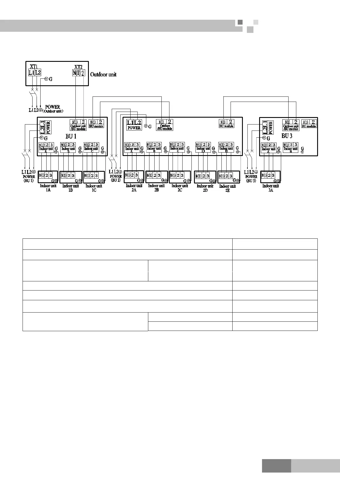
7 Electrical Wiring Work
7.1 Wiring Connection
The “L1”, “3” terminals are connected to the live wire, the “L2”,”N(1)” terminals are connected to the
neutral wire and the ”2” terminal is connected to the transmission line.
7.2 Requirements of Power Circuit and Cable
zH06,hP1 ycneuqerf dna esahP
V032/802 egatloV
Recommended cable of outdoor unit
(Pieces × Sectional area)
MULTIU48HP230V1BO
3×6.0 mm
2
Recommended cable of BU module (Pieces × Sectional area) 3×0.75 mm
2
Transmission line (Pieces × Sectional area) 2×1.5 mm
2
Recommended cable of indoor unit (Pieces × Sectional area) 4×0.75mm
2
Capacity of the air switch
MULTIU48HP230V1BO
50A
A01 eludom UB
Note:
The total length of the transmission line between the outdoor unit and the furthest BU module is not more
than 55m. Otherwise, the system cannot work possibility.
The specifications of the power cable and transmission line listed in the table above are determined based
on the maximum power (maximum amps) of the unit.
The specifications of the power cable listed in the table above are applied to the conduit-guarded
multi-wire copper cable (like, YJV copper cable, consisting of PE insulated wires and a PVC cable
ja
cket)
used at 40 and resistible to 90℃ ℃, and shall be at least those of ordinary polychloroprene sheathed cords.
If the working condition changes, they should be modified according to the related national standard.
The specifications of the air switch listed in the table above are applied to the breaker with the working
temperature at 40 . If the working condition changes, they should be modified according to the related℃
national standard.
 Loading...