i.
Use Item H parts to fix Control panel onto the right upper side of the Arch Unit.
j.
Use Item E parts to connect the M7-2-101500 Plate on the left and T7-2-10290
Arm together. (refer to fig. D step 10)
k.
Fix T7-2-10120 Guide. It can be only a little bit touched with the M7-2-101600
Left Bar or M7-2-101700 Right Bar.
l.
Connect the Power Cord to the terminal under the Upper Table Front.
m.
The installation of Arch unit is done. Turn on the machine for following
testing.
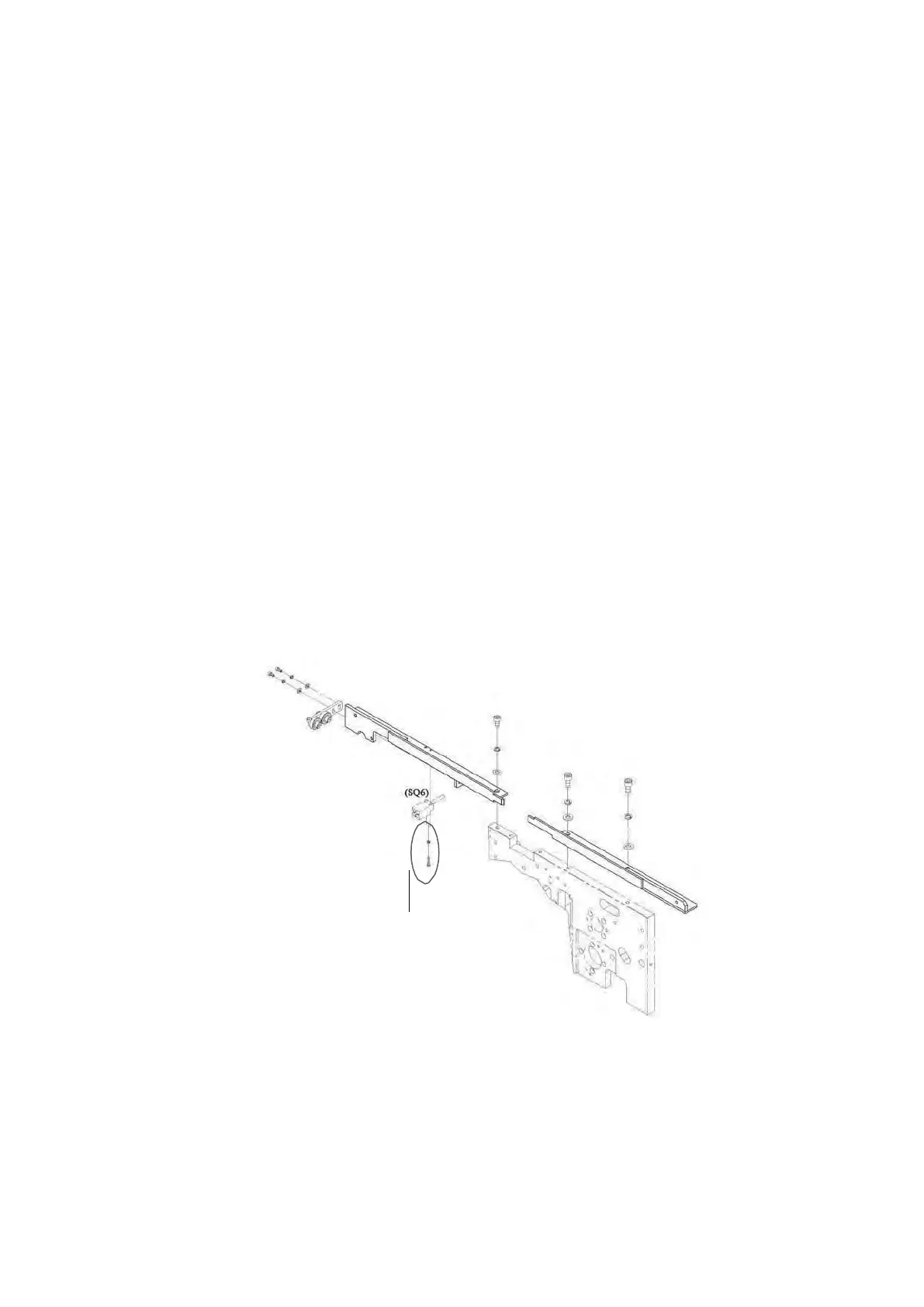
n.
If this machine is with SQ6 option (check chute home position sensor), fix the
SQ6 and make adjustment to have SQ6 is activated before the chute is 1mm
away from the home position. If the clearance is too big, it might cause feeding
failure; while if the clearance is too small, SQ6 might not able to be activated
well. (when testing SQ6, the power should be on so that the led on the SQ6 could
be activated.)
o.
If the width of arch is ≧1250mm, it‟s necessary to install Connecting Rod Group
(M7-2-400000) with Item F parts. (refer to fig. H); if the width of arch is 850mm
or 1050mm, it‟s necessary to install Connecting Rod Group (M7-2-400010) with
1set of Item F parts. (refer to fig. I)
p.
Put back the Upper Table Rear and close the Upper Table Front. Done.