483548 • Sensors for Model SP Fans, Rev. 2, November 2019 Copyright 2019 © Greenheck Fan Corporation4
As a result of our commitment to continuous improvement, Greenheck reserves the right to change specifications
without notice.
Product warranties can be found online at Greenheck.com, either on the specific product page or in the literature
section of the website at Greenheck.com/Resources/Library/Literature.
®
Phone: 715.359.6171 • Fax: 715.355.2399 • Parts: 800.355.5354 • E-mail: gfcinfo@greenheck.com • Website: www.greenheck.com
Our Commitment
AMCA Publication 410-96, Safety Practices for Users and
Installers of Industrial and Commercial Fans, provides
additional safety information. This publication can be obtained
from AMCA International, Inc. at www.amca.org.
Greenheck’s Centrifugal Ceiling Exhaust and Inline Cabinet
Fans catalog provides additional information describing the
equipment, fan performance, available accessories, and
specification data.
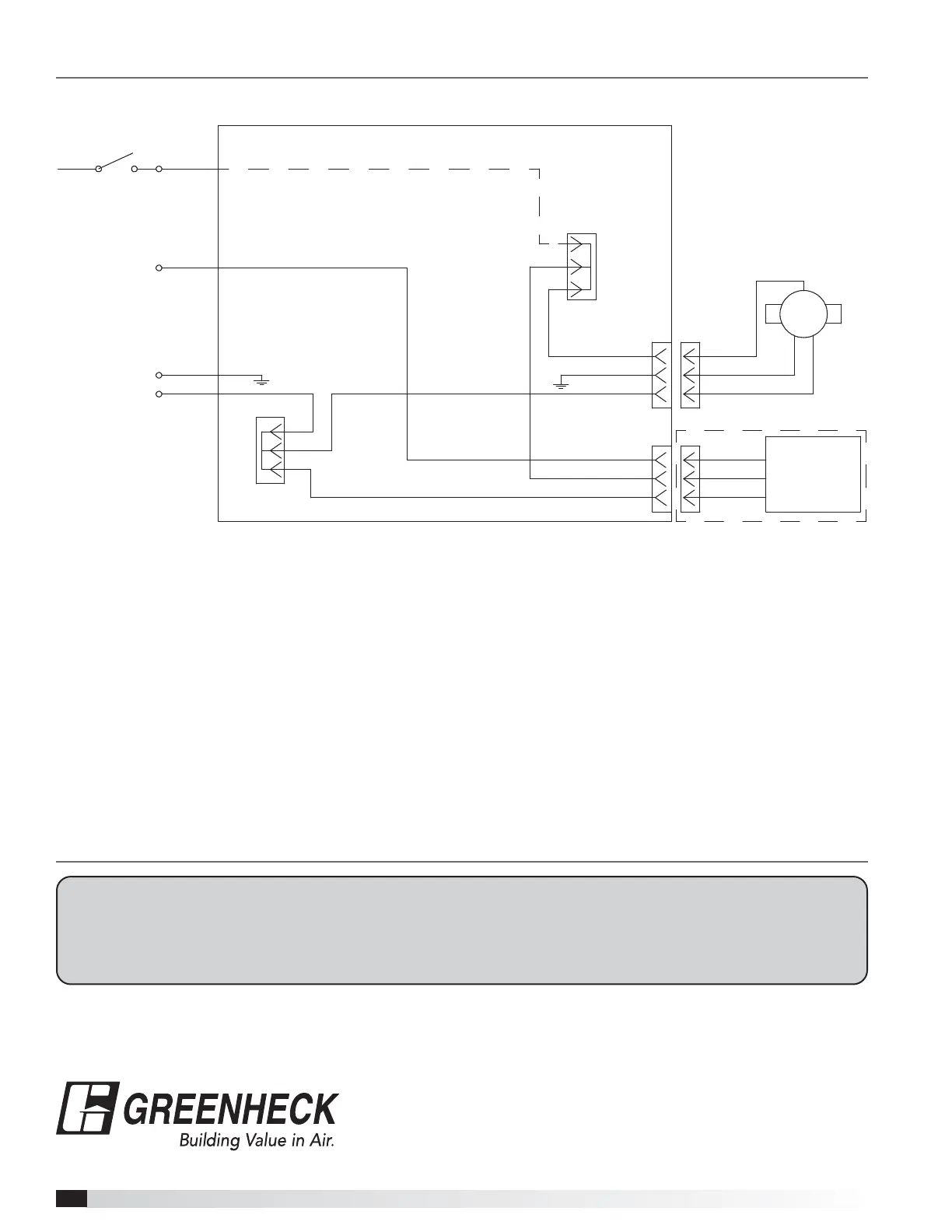
Wiring Diagram for Wall Switch Sensor Override
JUNCTION BOX
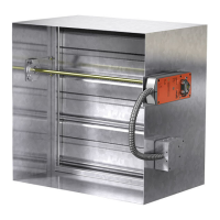
FAN
CUSTOMER
WALL SWITCH
L1 SWITCHED POWER
RED WIRE
CUSTOMER SUPPLIED
BLACK WIRE
GREEN WIRE
WHITE WIRE
GROUND (EARTH)
NEUTRAL WIRE
L2 CONSTANT POWER
BLACK WIRE
RED WIRE
WHITE WIRE
BLACK WIRE
RED WIRE
WHITE WIRE
OPTIONAL SENSOR:
MOTION
HUMIDITY, or
MOTION & HUMIDITY
BLACK WIRE
GREEN WIRE
WHITE WIRE
BLACK WIRE
GREEN WIRE
WHITE WIRE
LEVER NUT
LEVER NUT
FAN
ACC
1 L1 Switched Power: Red Wire - Customer connection for switched power to the fan
motor for high speed to be landed in lever nut connector.
2. L2 Constant Power: Black Wire - Provides customer connection for constant power to
the motion sensor.
3. L3 Neutral Power: White Wire - Provides customer connection for neutral power to the
fan motor.
4. Green Wire: Provides earth ground for customer connection.