High Volume, Low Speed Ceiling Fans12
®
Safety Retention Cable Installation
IMPORTANT: Do not put excessive tension on the
safety retention cable during installation. The safety
retention cable should be installed with a small amount
of slack in the cable to ensure proper functioning. Do
not allow the safety retention cable to contact any sharp
edges.
NOTE: Failure to install the safety retention cable will
result in voiding of the fan warranty.
Standard Steel Cable Clamp
The following instructions apply to standard fan
installations. For fans that were supplied with optional
Gripple
®
hardware, refer to the instructions on page 13.
Components required from Bag # 916290:
• U-Bolt Steel Cable Clamp (2)
Hardware/Tools Needed (Not Included):
• Torque Wrench
• 7/16 in. Socket and Wrench
• Cable Cutters (optional)
1. From the top of the downtube, pull the safety
retention cable until it is taut inside the downtube.
2. Wrap the loose end of the safety cable around
the mounting structure. Do not allow the cable to
come in contact with any sharp edges.
3. Align the loose end of the safety cable (referred to
as the dead-end) with the length of cable that is
wrapped around the mounting structure (referred
to as the live-end).
2. On the communication wiring terminal strip,
remove the 24V (brown-white) wire and cap with
a wire nut or heat shrink. Additionally, remove the
stranded silver drain wire that is attached to the
circuit board mounting screw and isolate from all
circuit board components using heat shrink.
3. Set dipswitch 2 as shown below. Dipswitch 2 is
used to set parameters that improve network
function and will need to be adjusted for all fans in
the network except for the first fan.
Position 1 – Off
Position 2 – Off
Position 3 – Off
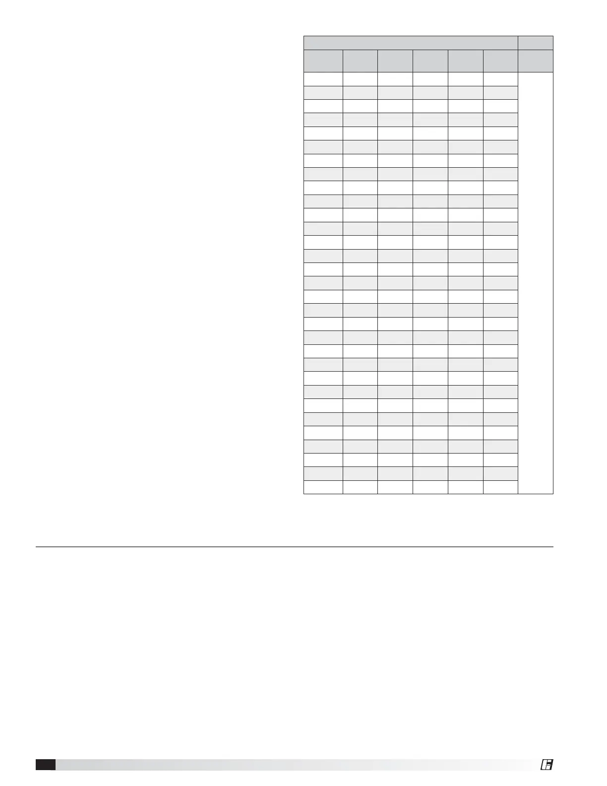
4. Adjust positions 1 – 5 on dipswitch 3 so that each
successive fan has a unique Modbus address. A
table with all possible Modbus addresses is shown
below.
IMPORTANT: Positions 6 – 8 are used to set parameters
needed for fan operation and should not be adjusted.
NOTE: It is good practice to use successive Modbus
addresses for networked fans, but this is not necessary
for proper functioning of the network.
4. Reinstall the front VFD cover.
Modbus Address Settings - Dipswitch 3
Modbus
Address
Position
1
Position
2
Position
3
Position
4
Position
5
Position
6, 7, 8
1 Off Off Off Off Off
Do Not
Modify
2 On Off Off Off Off
3 Off On Off Off Off
4 On On Off Off Off
5 Off Off On Off Off
6 On Off On Off Off
7 Off On On Off Off
8 OnOnOnOffOff
9 Off Off Off On Off
10 On Off Off On Off
11 Off On Off On Off
12 On On Off On Off
13 Off Off On On Off
14 On Off On On Off
15 Off On On On Off
16 On On On On Off
17 Off Off Off Off On
18 On Off Off Off On
19 Off On Off Off On
20 On On Off Off On
21 Off Off On Off On
22 On Off On Off On
23 Off On On Off On
24 On On On Off On
25 Off Off Off On On
26 On Off Off On On
27 Off On Off On On
28 On On Off On On
29 Off Off On On On
30 On Off On On On
31 OffOnOnOnOn