High Volume, Low Speed Ceiling Fans 13
®
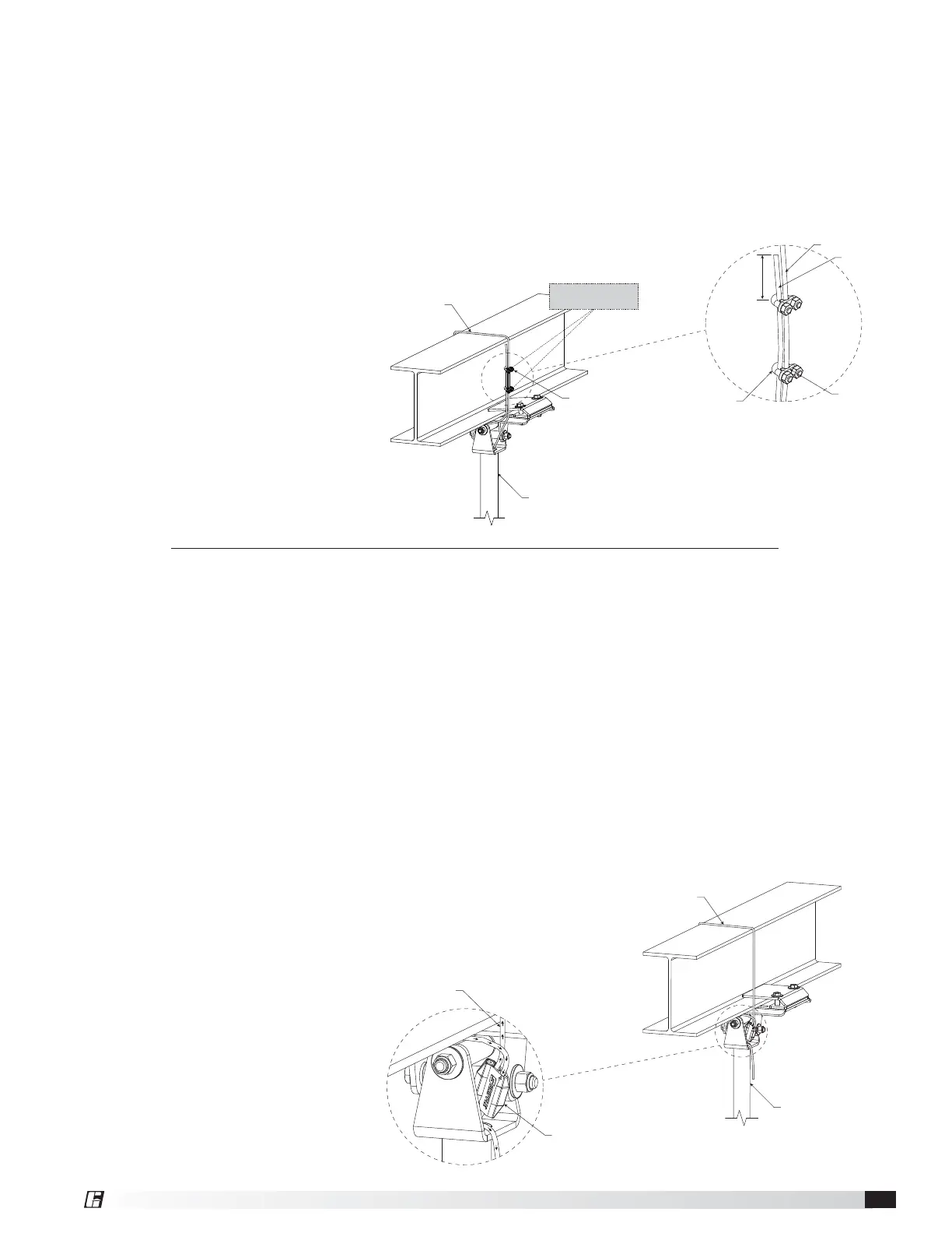
4. Attach the dead-end of the safety cable to the live-
end using the supplied 0.188 in. u-bolt steel cable.
IMPORTANT: The first steel cable clamp must be
installed a minimum of 5½ inches away from the dead-
end of the safety cable to ensure proper functioning.
IMPORTANT: Steel cable clamps are composed of two
parts: the u-bolt and the saddle. Steel cable clamps
must be installed with the u-bolt over the dead-end
of the safety retention cable and the saddle over the
live-end of the safety cable. Failure to install steel cable
clamps in this manner may result in unsafe operating
conditions. Refer to drawing below for
correct orientation.
5. Pull the dead-end of the safety
cable through the steel cable
clamps to tighten the cable.
The cable should be pulled taut,
leaving only a small amount
of slack in the cable to ensure
proper functioning.
6. Tighten the nuts on the steel cable clamps using a
7/16 in. socket and torque to 54 in∙lbf (6.10 N∙m),
alternating between nuts until reaching proper
torque.
7. Cut or organize excess safety cable to ensure it
does not interfere with fan performance. Make
sure to leave at least 5½ inches of cable between
the dead-end of the cable and the first steel cable
clamp to ensure proper functioning.
DOWNTUBE SAFETY CABLE
DOWNTUBE & MOUNT ASSEMBLY
CABLE CLAMP
CABLE CLAMP
SADDLE
CABLE CLAMP U-BOLT
DEAD END
LIVE END
TORQUE TO 54 IN∙LBF
(6.10 N∙m)
5-1/2 IN.
MIN.
Gripple
®
Hardware (Optional)
Components required from Bag # 915067:
• No. 4 Gripple
®
Connector (1)
Hardware/Tools (Not Included):
• 1/16 in. Allen Wrench (optional)
• Cable Cutters (optional)
1. From the top of the downtube, pull the safety
retention cable until the cable is taut inside the
downtube.
2. Insert the loose end of the safety cable into the No.
4 Gripple connector. Note that the cable will only
feed through the Gripple connector in one direction
(marked on the Gripple connector with an arrow).
3. Slide the No. 4 Gripple connector down the safety
cable until it is located near the opening at the top
of the downtube.
4. Wrap the loose end of the
safety cable around the
mounting structure. Do not
allow the cable to come in
contact with any sharp edges.
5. Insert the loose end of the
safety cable into the open hole
of the No. 4 Gripple connector.
Note that the cable will only feed through the
Gripple connector in one direction (marked on the
Gripple connector with an arrow).
6. Pull the loose end of the safety cable through the
Gripple connector to tighten the cable. The cable
should be pulled taut, leaving only a small amount
of slack in the cable to ensure proper functioning.
7. Cut or organize excess safety cable to ensure it
does not interfere with fan rotation.
NOTE: If necessary, the safety cable can be loosened
by inserting the long end of a 1/16 in. allen wrench into
either of the pin holes on the No. 4 Gripple connector
and pulling the cable in the opposite direction of the
arrow marked on the Gripple connector.
DOWNTUBE SAFETY CABLE
DOWNTUBE SAFETY CABLE
DOWNTUBE & MOUNT ASSEMBLY
NO. 4 GRIPPLE