R
Roberta CuevasSep 23, 2025
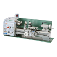
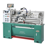
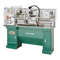
What to do if quick-change gear change dials won't shift on my Grizzly Lathe?
- JJeremy HubbardSep 23, 2025
If the quick-change gear change dials on your Grizzly Lathe won't shift into position, it's likely because the gears are not aligned inside the headstock or quick change gearbox. Rotate the spindle by hand while applying light pressure on the dial until the gear falls into place.