O
Oscar NelsonAug 27, 2025
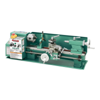
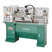
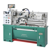
Why does my Grizzly Lathe vibrate upon startup and while running?
- KKevin BarreraAug 27, 2025
If your Grizzly Lathe vibrates upon startup and while running, it could be due to: an unbalanced workpiece (re-install as centered as possible with the spindle bore); loose or damaged V-belts (re-tension/replace as necessary); V-belt pulleys not properly aligned (align them); a worn or broken gear (inspect and replace if needed); an unbalanced chuck or faceplate (re-balance or seek help from a local machine shop); gears not aligned in the headstock or no backlash (adjust change gears and establish backlash); a broken gear or bad bearing (replace); the workpiece hitting a stationary object (stop the lathe and correct the interference); or faulty spindle bearings (reset spindle bearing preload or replace worn bearings).