Model G0776 (Mfd. Since 7/14)
-57-
Thread Dial Chart
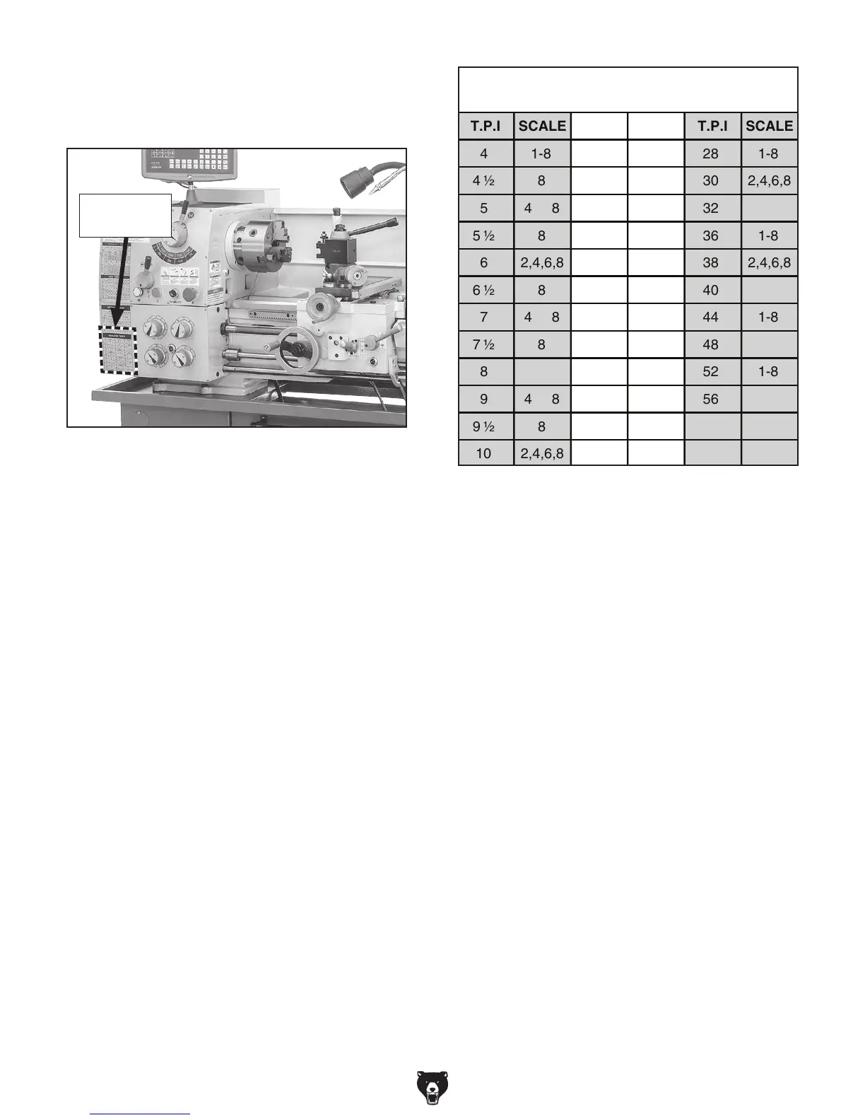
The thread dial chart is located on the headstock
cover, as shown in Figure 83.
Figure 83. Thread dial chart and thread dial
locations.
Thread Dial
Chart
56
52
48
44
40
38
36
32
30
28
26
24
22
20
19
18
15
14
4 813
12 1-8
4 8
2,4,6,810
8
4 8
9 ½
8
4 8
86 ½
2,4,6,86
8
4 85
7
5 ½
4 ½ 8
1-8
T.P.I SCALESCALET.P.ISCALET.P.I
INDICATOR TABLE
7 ½
9
11
16
8
2,4,6,8
4 8
2,4,6,8
4 8
1-8
2,4,6,8
2,4,6,8
1-8
2,4,6,8
1-8
2,4,6,8
1-8
1-8
4
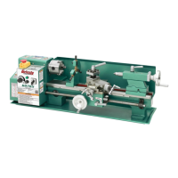
Figure 84. Thread dial chart.
Find the TPI (threads per inch) that you want
to cut in the left columns (under TPI, shown in
Figure 84), then reference the dial number in the
right columns (under Scale). The dial number
indicates when to engage the halfnut for a specific
thread pitch as indicated by the thread dial (see
Figure 82 on Page 56).
Note: The blanks in the chart indicate that the
half nut may be engaged in any position, even in
between marks.
Note: If you do not want to use the chart, you can
cut any thread by starting and stopping on the 1
on the thread dial.