-52-
Model G0776 (Mfd. Since 7/14)
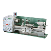
3. Locate applicable change gear on chart in
Figure 69 on Page 51 (in this case it is the
48T gear).
4. Install 48T gear in lower "Z" position so it
meshes with 127T gear (refer to Power Feed
Configuration for details).
5. Rotate spindle by hand to verify no binding
exists.
6. Move feed dials to positions B5SI, as shown
in Figure 70.
—"B5" indicates that the dial marked A–E
must be set to the "B" position, and the dial
marked 1–5 must be set to the "5" position.
—The sub-row "I" indicates the dial marked
I–II must be set to the "I" position.
—Because the feed rate is in inches (stan-
dard) the dial marked S/M must be set to
the "S" position.
The carriage is now set up for a power feed rate
of 0.0021 in./rev.
Figure 70. Feed control settings for a 0.0021"
carriage feed rate.
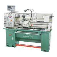
The end gears must be correctly setup for power
feed, inch, or metric threading operations. Use the
photo below to identify the upper 24T/48T gear,
middle 120T/127T change gears, and lower "Z"
gear, which are also referenced on the headstock
feed and threading charts.
The following subsections explain how to config-
ure the end gears.
End Gears
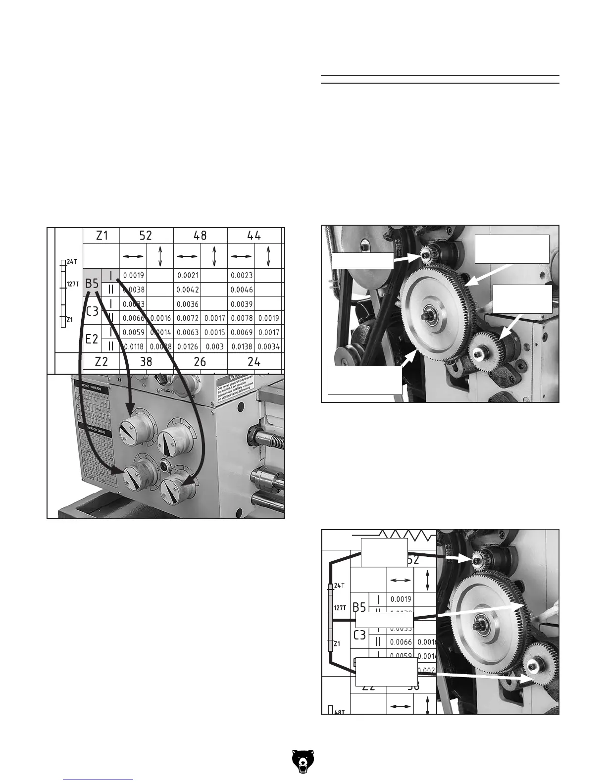
Power Feed Configuration
Install either a 24T or 48T gear in the upper posi-
tion and mesh it with the 127T gear. Install the
appropriate gear in the "Z" position for the desired
feed rate and mesh it with the 127T gear (see
Figure 72).
Figure 71. Change gear identification.
127T Change
Gear
120T Change
Gear
Lower "Z"
Gear
Figure 72. Power feed chart change gears.
Upper Gear
127T Gear
Upper
Position
"Z" Position
Gear
 Loading...