-50-
Model G0776 (Mfd. Since 7/14)
Both the carriage and cross slide have power feed
capability when the carriage is engaged with the
feed rod. The rate that these components move
per revolution of the feed rod is controlled by the
quick-change gearbox dial positions and the end
gear configuration.
The feed per revolution and the spindle speed
must be considered together—this is the feed
rate. The sources you use to determine the opti-
mum spindle speed for an operation will also
provide the optimal feed to use with that spindle
speed.
Often, the experienced machinist will use the
feeds and speeds given in their reference charts
or web calculators as a starting point, then make
minor adjustments to the feed rate (and some-
times spindle speed) to achieve the best results.
The carriage can alternately be driven by the
leadscrew for threading operations. However, this
section only covers the use of the power feed
option for the carriage and cross slide compo-
nents for non-threading operations. To learn how
to power the carriage for threading operations,
refer to Threading on Page 55.
Power Feed
If the feed selection lever and the half nut
are engaged at the same time, machine
damage could occur. Even though there is
a lock-out device to prevent this, it could
break if forced.
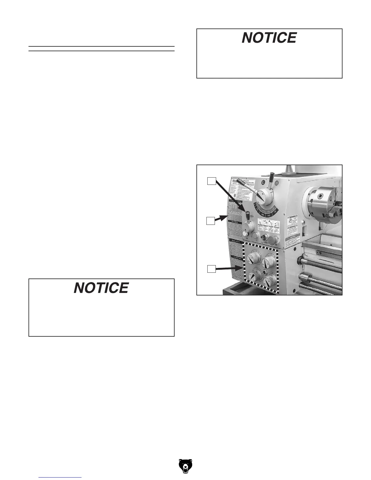
Power Feed Controls
Use Figures 66–67 and the following descrip-
tions to understand the power feed controls.
Note: Before using power feed, you may have to
reconfigure the end gears, depending on how they
are set up. Refer to End Gears on Page 52 for
detailed instructions.
Figure 66. Power feed controls on the
headstock.
To avoid damaging the lathe, ALWAYS make
sure the spindle is completely stopped
BEFORE using the headstock controls to
make changes.
A. Feed Direction Lever: Selects the direction
for power feed. When the lever is positioned
as shown in Figure 66, the carriage will move
to the left along the bed, or the cross feed will
travel toward the front of the lathe.
B. Feed Rate Chart: Displays the settings
for the quick-change gearbox dials for the
selected feed rate. Refer to Setting Power
Feed Rate subsection on the next page for
detailed instructions.
C. Quick-Change Gearbox Dials: Position
these as indicated on the charts to choose
different feed rates.
A
B
C