
D
Debra RossAug 17, 2025
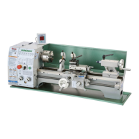
Why does my Grizzly G0824 vibrate so much?
- JJennifer JohnsonAug 17, 2025
Excessive vibration in your Grizzly Lathe can stem from several issues. It could be due to an unbalanced workpiece, which requires re-centering with the spindle bore. Alternatively, the workpiece might be hitting a stationary object, which requires immediate correction. Other potential causes include loose or damaged V-belts needing re-tensioning or replacement, misaligned V-belt pulleys, an unbalanced chuck or faceplate needing rebalancing, gears not aligned in the headstock, or worn/broken gears or bearings requiring replacement. It could also be the spindle bearings, which may need preload resetting or replacement.