-20-
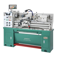
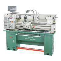
Model G0824 (Mfd. Since 12/16)
With the exception of the handwheels and DRO
unit, the Model G0824 is shipped fully assembled.
To assemble lathe:
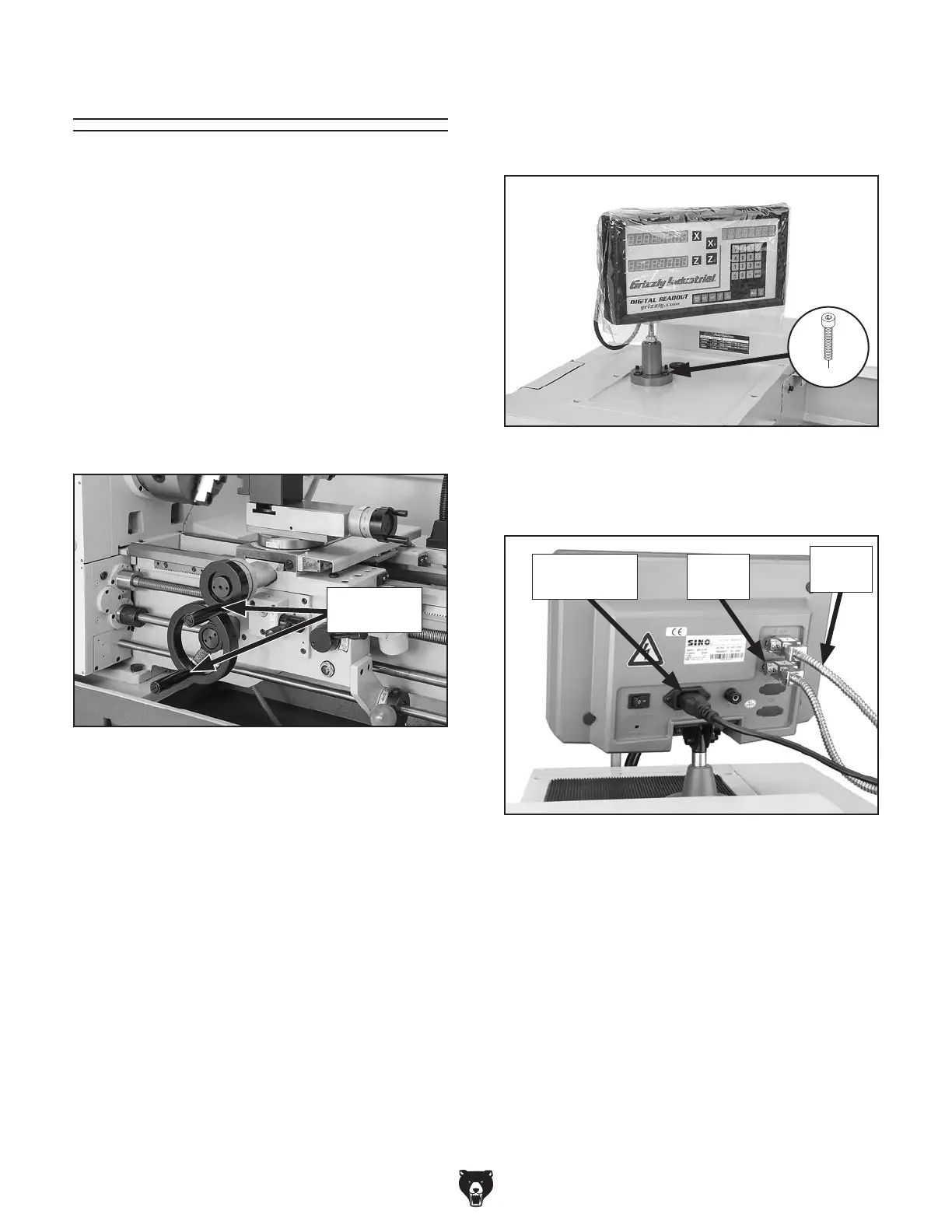
1.
Thread handles into handwheels, as shown
in Figure 14.
3
. Connect X- and Z-axis cables and power cord
to back of DRO unit, as shown in Figure 16.
Figure 16. DRO electrical connections.
DRO Power
Cord
X-Axis
Cable
Z-Axis
Cable
Figure 14. Handwheel handles installed.
2. Secure DRO assembly to threaded mount-
ing holes in headstock cover, using (3)
pre-installed M8-1.25 x 20 cap screws
(see Figure 15).
Figure 15. DRO unit mounted to headstock.
x 3
Handwheel
Handles
Assembly
The machine must be fully assembled before it
can be operated. Before beginning the assembly
process, refer to
Needed for Setup and gather
listed items. To ensure the assembly process
goes smoothly, first clean any
parts that are cov-
ered or coated in heavy-duty rust preventative (if
applicable).
 Loading...