-54-
Model G0824 (Mfd. Since 12/16)
The following subsections describe how to use
the threading charts and controls to set up the
lathe for a threading operation. If you are unfamil-
iar with the process of cutting threads on a lathe,
we strongly recommend that you read books,
review industry trade magazines, or get formal
training before attempting any threading projects.
Headstock Threading Controls
The threading charts on the headstock face dis-
play the settings for inch and metric threading.
Using the controls on the lathe, follow the exam-
ple below to understand how to set up the lathe
for the desired threading operation.
To set dials for 18 TPI:
1. Locate 18 TPI on the inch threading chart
shown in Figure 81.
Threading
Arm-Support
Hex Nut
Gear-Support
Hex Nut
60T Gear
54T Gear
127T Gear
(In Rear)
120T Gear
(In Front)
Figure 80. 60T & 54T gears installed.
11.
Rotate 127T gear up against 60T gear until
they mesh with 0.002" to 0.004" backlash.
12
. Tighten arm support hex nut (see Figure 80).
13.
Secure arm support cap screw (see Figure 78).
14.
Re-install end gear cover.
10. Slide 127T gear against lower 54T gear
(see Figure 80) until they mesh with 0.002"
to 0.004" backlash, then tighten gear support
hex nut.
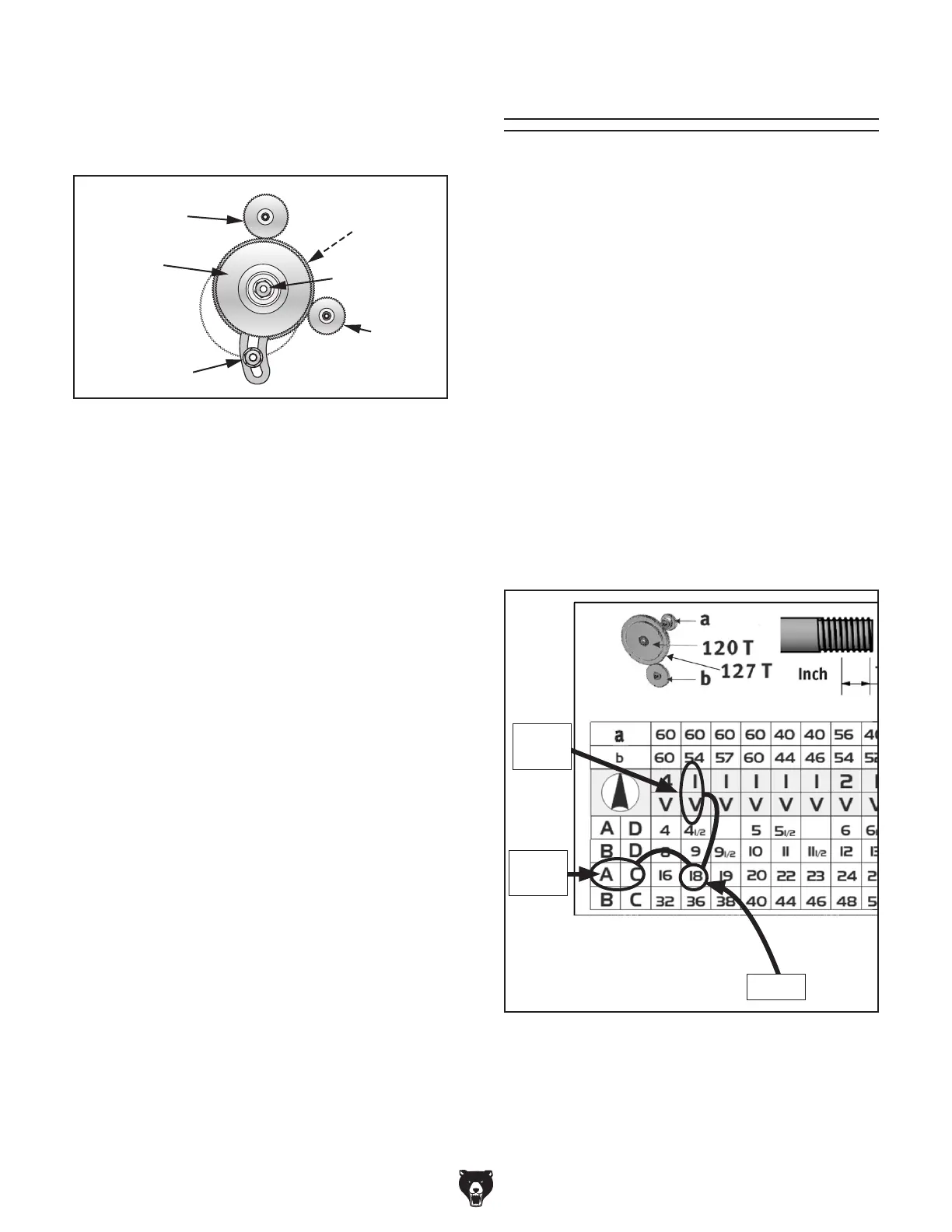
Figure 81. 18 TPI and corresponding dial
positions.
1 & V
Dials
18 TPI
A & C
Dials
2. Install 60T and 54T gears, as instructed
in End-Gear Configuration Example on
Page 53.
 Loading...