Model G0776 (Mfd. Since 7/14)
-45-
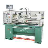
The carriage and compound rest have locks that
can be tightened to provide additional rigidity dur-
ing operation, especially during heavy cuts.
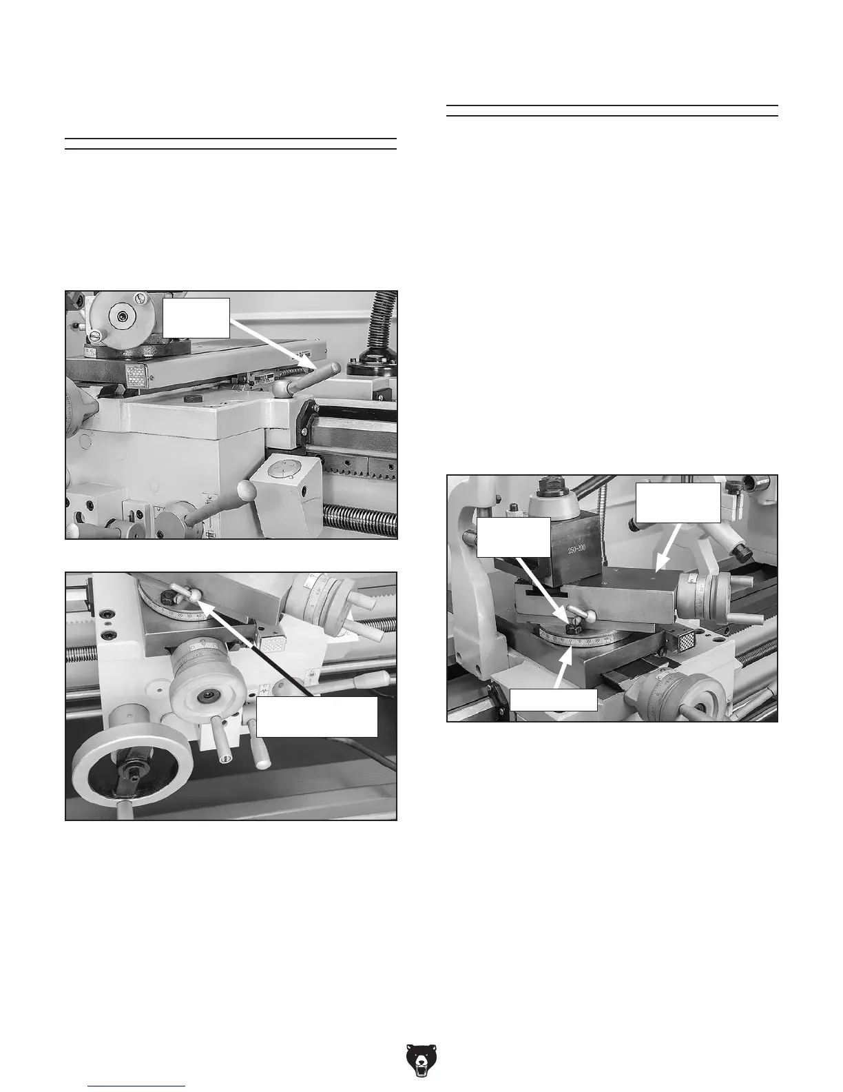
See Figures 54–55 to identify the locks for each
device.
Carriage & Slide
Locks
Figure 55. Location of compound rest lock.
Compound Rest
Lock
Figure 54. Location of carriage lock.
Carriage
Lock
2. Rotate rest to desired angle, as indicated
by scale at base, then retighten the two hex
nuts.
Tip: The first time you set the angle of the
compound rest for cutting threads, mark the
location on the cross slide as a quick refer-
ence point. This will allow you to quickly
return the compound rest to that exact angle
the next time you need to cut threads.
The compound rest handwheel has an indirect-
read graduated scale. This means that the dis-
tance shown on the scale represents the actual
distance the cutting tool moves. The base of the
compound rest has another graduated scale used
for setting the cutting tool to a specific angle.
Graduated Dial
Increments ................................. 0.001" (0.03mm)
One Full Revolution ................... 0.100" (2.54mm)
Tool Needed Qty
Open-End Wrench 19mm .................................. 1
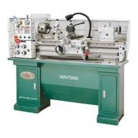
To set compound rest at a certain angle:
1. Loosen two hex nuts at base of compound
rest (1 of 2 shown in Figure 56).
Figure 56. Compound rest angle adjustments.
Compound Rest
Hex Nuts
(1 of 2)
Compound
Rest
Angle Scale