-4-
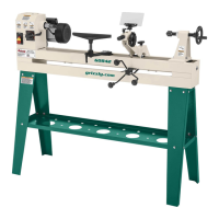
Model G0776 (Mfd. Since 7/14)
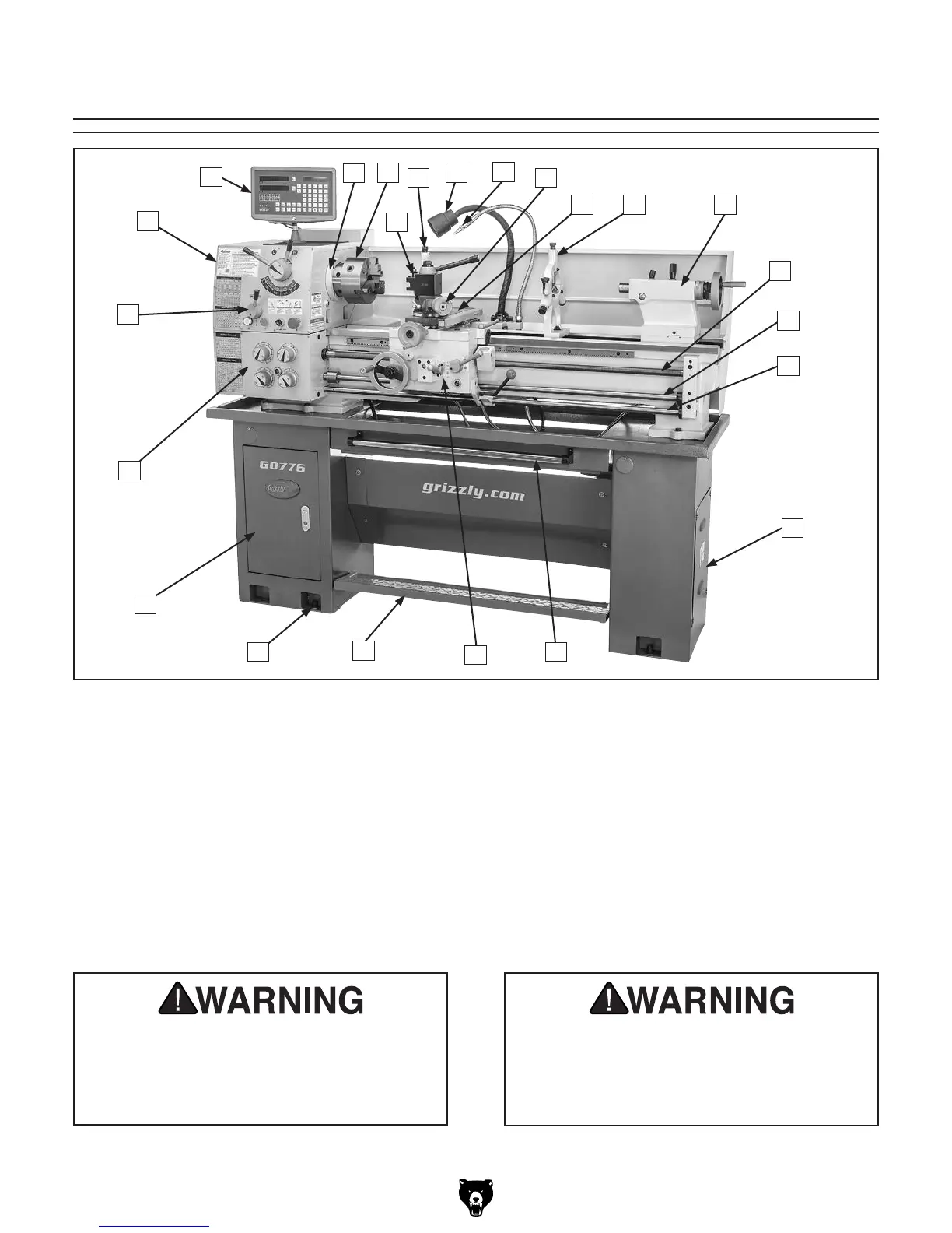
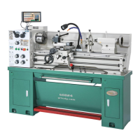
Identification
Serious personal injury could occur if
you connect the machine to power before
completing the setup process. DO NOT
connect power until instructed to do so later
in this manual.
Untrained users have an increased risk
of seriously injuring themselves with this
machine. Do not operate this machine until
you have understood this entire manual and
received proper training.
B
D
C
H
J K
L
M
S
T
U
V
W
O
N
E
F
G
A
R
P
Q
I
A. Headstock
B. DRO Unit
C. D1-4 Camlock MT#5 Spindle
D. 3-Jaw Chuck 6"
E. Quick-Change Tool Post
F. Follow Rest
G. Halogen Work Lamp
H. Coolant Valve and Nozzle
I. Compound Rest
J. Cross Slide
K. Steady Rest
L. Tailstock (see Page 6 for details)
M. Longitudinal Leadscrew
N. Feed Rod
O. Control Rod
P. Coolant Reservoir and Pump Access
Q. Chip Tray
R. Carriage (see Page 6 for details)
S. Foot Brake
T. Stand Mounting Points
U. Storage Cabinet
V. Quick-Change Gearbox Controls (see Page 5
for details)
W. Headstock Controls (see Page 5 for details)