-26-
Model G0776 (Mfd. Since 7/14)
2. Read and follow safety instructions at begin-
ning of manual, take all required safety pre-
cautions, and make sure all previous prepa-
ration steps discussed in this manual have
been followed and completed.
3. Clear away all tools and objects used during
assembly, lubrication, and preparation.
4. Make sure chuck and jaws, if installed, are
secure (refer to Chuck Installation on Page
31).
Note: If a chuck is not installed on the lathe,
you do not need to install one for this test.
Test Run
Once assembly is complete, test run the machine
to ensure it is properly connected to power and
safety components are functioning correctly.
If you find an unusual problem during the test run,
immediately stop the machine, disconnect it from
power, and fix the problem BEFORE operating the
machine again. The
Troubleshooting
table in the
SERVICE section of this manual can help.
DO NOT start machine until all preceding
setup instructions have been performed.
Operating an improperly set up machine
may result in malfunction or unexpect-
ed results that can lead to serious injury,
death, or machine/property damage.
Serious injury or death can result from
using this machine BEFORE understanding
its controls and related safety information.
DO NOT operate, or allow others to operate,
machine until the information is understood.
NOTICE
NEVER shift lathe gears when lathe is
operating, and make sure both half-nut lever
and feed selection lever are disengaged
before you start lathe! Otherwise carriage
may feed into chuck or tailstock and cause
severe damage.
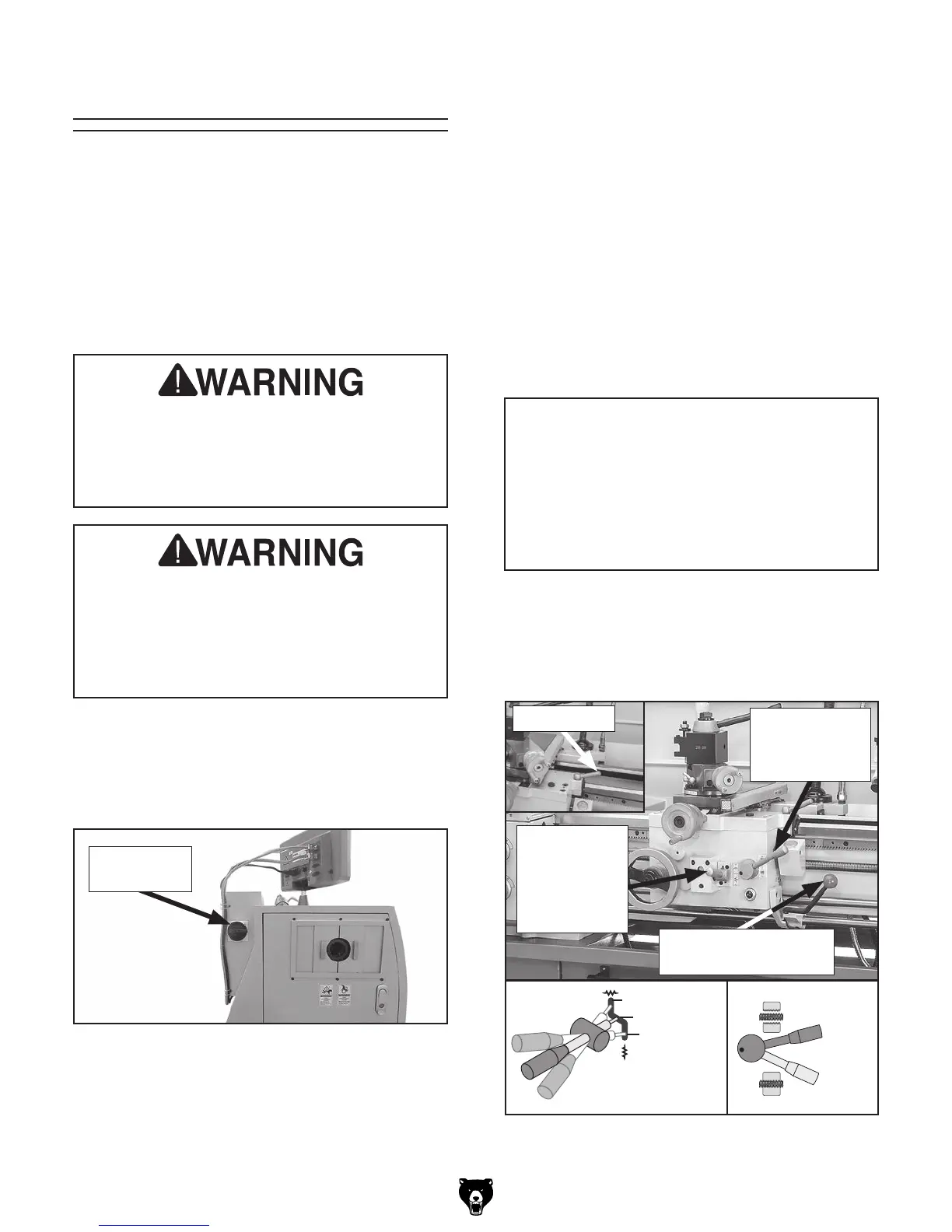
5. Disengage half-nut lever and feed selection
lever (see Figure 22), and make sure saddle
lock is loosened to allow leadscrew or feed
rod to move apron if required.
Figure 22. Apron controls.
Engaged
Halfnut
Lever
Disengaged
Saddle Lock
Feed
Selection
Lever is
Horizontal
(Disengaged)
Half-Nut Lever
is Pulled Up
(Disengaged)
Spindle Lever
(OFF, center position)
Disengaged
Feed Selection
Lever
Carriage
Figure 21. Location of the main power switch.
Main Power
Switch
To test run your machine:
1. Make sure the main power switch (see
Figure 21) is turned OFF.