Model G0776 (Mfd. Since 7/14)
-85-
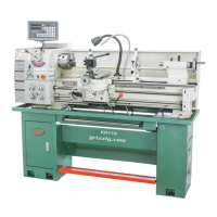
6. Place wood block over outboard end of
spindle. Tap it a few times with dead blow
hammer (see Figure 144). Your goal is to
slide spindle forward just enough to introduce
spindle end-play that you can feel by hand.
Figure 144. Unseating spindle bearings to intro-
duce spindle end-play.
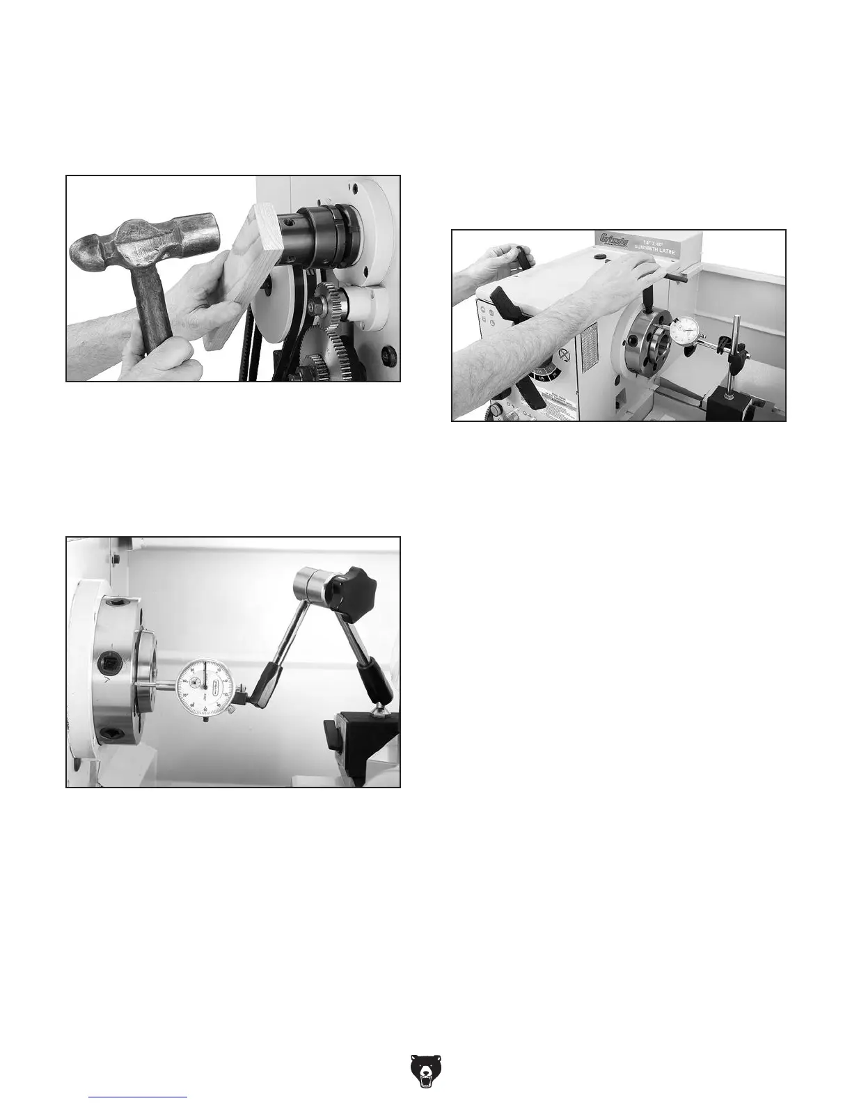
7. Place dial indicator on cross slide and move
carriage toward headstock until contact point
of indicator touches spindle face (see Figure
145).
Figure 145. Dial indicator setup.
8. Move carriage an additional 0.100" toward
headstock, and zero dial indicator.
While tightening spanner nuts, rock spindle
back and forth slightly with cam key to make
sure spindle tapered roller bearings seat
properly in their races.
When dial indicator needle stops moving,
there will be zero spindle end-play and no
bearing preload. It is essential that you find
this point without tightening spanner nut
too much and inadvertently pre-load spindle
bearings.
If you think you have gone past zero end-play
point, unload bearings by repeating Steps
5–6, then re-tighten inner spanner nut until it
has reached zero end play position.
10. Tighten spanner nut an additional
1
⁄16-turn.
11. Without allowing inner spanner nut to tighten
any farther, tighten outer spanner nut against
inner nut.
Do not overtighten outer spanner nut because
additional preload can force bearings even
tighter against races in headstock and cause
headstock to compress or crack, or bearing
may quickly fail.
12. Re-install outboard gear cover.
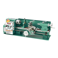
Figure 146. Adjusting spindle bearings.
9. Insert chuck wrench into a cam socket to pre-
vent spindle from turning, then tighten inner
spanner nut until dial indicator needle just
stops moving (see Figure 146).
Note: For convenience and accuracy, we
recommend having another person watch the
dial while you tighten the inner spanner nut.