EasyManua.ls Logo

Grizzly G1035 User Manual

Grizzly G1035
64 pages
To Next Page IconTo Next Page
Page #1 background imageLoading...
Page #1 background image
8DENG><=I&..%7N<G>OOAN>C9JHIG>6A!>C8#G:K>H:9?JC:!'%&'7A
WARNING: NO PORTION OF THIS MANUAL MAY BE REPRODUCED IN ANY SHAPE
OR FORM WITHOUT THE WRITTEN APPROVAL OF GRIZZLY INDUSTRIAL, INC.
7A),%-EG>CI:9>CI6>L6C
MODEL G1035/G1035P
1
1
2 HP SHAPER
OWNER'S MANUAL
(For models manufactured since 04/10)
&,,((*

Other manuals for Grizzly G1035

Questions and Answers:

Grizzly G1035 Specifications

General IconGeneral
Disc Diameter6 inches
Belt Size4 x 36 inches
Disc Speed3450 RPM
Voltage110V
Arbor Size1/2 inch
Weight44 lbs
TypeBenchtop Belt/Disc Sander

Summary

Introduction to the Grizzly Shaper

Manual Accuracy and Machine Updates

Ensures manual accuracy and notes potential differences between the manual and the actual machine due to continuous improvement.

Contact Information for Support

Provides contact details for Grizzly Industrial's technical support and documentation departments for assistance.

Machine Description and Features

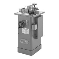
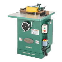
Details the Model G1035/G1035P shaper, its motor, speeds, table, and interchangeable spindles.

Machine Data Sheet

Section 1: Safety

Safety Instructions for Machinery

Critical safety instructions for operating the shaper, including warnings about electrical hazards and operator training.

Additional Safety for Shapers

Specific safety precautions for shaper operations, covering cutter exposure, hand safety, and workpiece handling.

Section 2: Power Supply

Power Supply Availability and Requirements

Details requirements for 120V and 240V power supplies, including circuit ratings and grounding.

Grounding Requirements and Extension Cords

Explains proper grounding procedures and recommendations for using extension cords, if necessary.

Voltage Conversion Procedure

Instructions for converting the machine's voltage, emphasizing the need for qualified personnel.

Section 3: Setup

Items Needed for Setup

Lists tools and materials required but not included with the machine for setup.

Unpacking and Inventory

Guidance on safely unpacking the machine and verifying all components are present.

Machine Cleanup Procedures

Steps for cleaning rust preventative from unpainted surfaces using appropriate cleaners.

Site Considerations for Installation

Factors to consider for machine placement, including weight load, space, environment, and lighting.

Machine Assembly Steps

Instructions for assembling components like the motor braces, switches, and handwheel.

Spindle Installation

Procedure for Installing a Shaper Spindle

Step-by-step guide on how to correctly install spindles, including drawbar and nut tightening.

Table Inserts Adjustment

Leveling the Cast Iron Insert

Instructions on how to adjust the cast iron table insert to be flush with the table surface.

Fence Assembly Installation

Attaching the Fence Assembly to the Table

Guidance on how to correctly attach the fence assembly to the shaper table.

Safety Guard Assembly

Assembling the Shaper Safety Guard

Steps for assembling the safety guard components onto the shaper.

Hold-Downs Assembly

Assembling and Positioning Hold-Downs

Instructions for assembling the hold-down system and positioning them for workpiece support.

Dust Collection Setup

Power Connection and Disconnection

Connecting the Machine to Power

Steps for safely connecting the shaper to the power supply.

Disconnecting the Machine from Power

Procedure for safely disconnecting the shaper from the power source.

Test Run Procedure

Performing a Test Run of the Machine

Steps to verify the shaper operates correctly, checking spindle rotation and noise.

Section 4: Operations

Operation Overview and Basic Understanding

Provides a basic understanding of how the shaper is used during operation.

Basic Controls and Safety Features

Describes essential controls like the forward/reverse switch and spindle height lock, plus disabling the switch.

Workpiece and Cutter Inspection

Guidance on inspecting workpieces for safety and understanding cutter rotation direction.

Speed and Cutter Adjustments

Instructions for changing spindle speeds and installing cutters onto the shaper spindle.

Fence and Spindle Height Adjustments

Procedures for adjusting the fence boards and the spindle height for various operations.

Box Guards for Shaper Safety

Straight Shaping Techniques

Shaping Small Stock Safely

Rub Collars for Shaping

Irregular Shaping Procedures

Using a Starting Pin for Irregular Shaping

Guidance on using a starting pin for safe irregular shaping operations.

Pattern Work Techniques

Section 5: Accessories

Rub Collar Sets for Shaping

Details on various rub collar sets for curved and irregular shaping.

Mobile Base and Cast Iron Wing

Information on accessories like the mini mobile base and cast iron table wing.

Bit Spindle for Router Bits

Description of the bit spindle accessory for using router bits with the shaper.

Dust Collection Accessories

Lists dust collection components such as hoods, hoses, and clamps.

Baby Power Feeder

Information on the power feeder accessory for increased production and safety.

Shaper Handbook

Reference to the Shaper Handbook for techniques and detailed instructions.

Recommended Maintenance Products

Lists recommended products for protecting unpainted cast iron and steel parts.

Eye Protection and Respirators

Details various types of safety glasses, face shields, and respirators for user protection.

Section 6: Maintenance

Maintenance Schedule and Cleaning

Outlines daily, weekly, and monthly maintenance checks and cleaning procedures.

Lubrication and Bearing Maintenance

Instructions for lubricating the spindle slide/leadscrew and replacing spindle bearings.

V-Belt Tension and Replacement

Guidance on checking V-belt tension and replacing it when necessary.

Section 7: Service

Troubleshooting Common Problems

Provides a guide to diagnosing and solving issues related to motor, electrical, and operation problems.

Table Insert Adjustment

Leveling the Insert Ring with the Table

Procedure to ensure the table insert ring is level with the shaper table surface.

Fence Board Alignment

Pulley Alignment

Checking Pulley Coplanarity

Method to check if the motor and spindle pulleys are aligned and coplanar.

Adjusting Pulleys Parallel

Aligning Pulleys

Gib Adjustment

Checking and Adjusting Gibs

Steps to check gib adjustment for slide smoothness and adjust set screws accordingly.

Section 8: Wiring

Wiring Safety Instructions

Critical safety guidelines for working with the machine's electrical wiring.

Wiring Diagram and Connections

Illustrates the wiring diagram for 120V and 240V configurations and connection points.

Section 9: Parts

Main Parts List

Exploded view and list of main components of the shaper.

Motor Parts List

Diagram and list of individual parts for the shaper's motor assembly.

Spindle Parts List

Diagram and list of components related to the shaper's spindle.

Safety Guard Parts List

Diagram and list of parts for the safety guard assembly.

Hold-Downs Parts List

Diagram and list of components for the hold-down system.

Miter Gauge Parts List

Diagram and list of parts for the miter gauge.

Label Placement Guide

Warranty and Returns Information

Related product manuals