Do you have a question about the Grizzly G1024 and is the answer not in the manual?
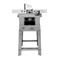
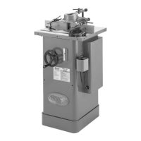
Essential guidance for safe and efficient operation of the Model G1024 Shaper.
Read the manual and understand the tool's applications, limitations, and hazards.
Ensure all guards are in place and in proper working order for safe operation.
Properly ground all tools, using a grounded outlet or adapter.
List of parts to check after unpacking for assembly.
Steps and precautions for cleaning the machine surfaces before assembly.
Information on the required floor load capacity for the shaper's placement.
Guidance on ensuring adequate space around the shaper for safe operation.
Details on the shaper's power requirements and recommended circuit protection.
Instructions for proper grounding of the shaper for electrical safety.
Instructions for assembling the shaper's stand, including attaching feet and crossbars.
Steps for assembling and adjusting the shaper's two-piece adjustable fence.
Instructions for attaching and adjusting the clear acrylic safety guard.
Never attempt to clear scraps or perform maintenance while the machine is running.
Ensure hands remain at least 12 inches away from the cutting edges during operation.
Always feed the workpiece opposite the direction of the cutter's rotation for control.
Instructions for adjusting the shaper's two-piece fence for precise cuts.
Steps for installing and securing shaper cutters onto the spindle.
How to adjust the vertical height of the shaper spindle.
Using the forward/reverse switch to control cutter rotation direction.
Details on selecting and using rub collars to limit cut depth and for pattern work.
Illustrates different positions for using rub collars with shaper cutters.
Using rub collars with patterns for shaping duplicate pieces or irregular shapes.
Instructions for shaping straight stock using the fence assembly.
Techniques for freehand shaping using starting pins and rub collars.
Lubrication points and frequency for the shaper's moving parts.
Inspecting and maintaining the shaper's V-belt for proper operation.
Exploded diagram of the main body assembly with part numbers.
Detailed list of parts for the Model G1024 Shaper.
| Brand | Grizzly |
|---|---|
| Model | G1024 |
| Category | Power Tool |
| Language | English |